 LSS 4
LSS 4Grids
Grids allow you to draw LED segments precisely aligned to various grid patterns, making the drawing process much easier. You can define multiple types of grid patterns in LSS4 Mapping.
Turn Grid On/Off
In the Strips section of the menu you can turn on or off all the grids in the workspace.
Grid On/Off in the menu
Grid Settings
In the middle section of the Grid Settings window, you can see a list of all added grids. To modify the properties of a grid, simply select it from this list.

Grid menu with the list of grids
Grid Types
There are three special types of grids in the Mapping window. After selecting Add Cartesian, Add Polar, or Add Custom, you can use the left mouse button to add a new grid to the Strip Editor.
You can set the number of points for each type of grid and adjust its exact placement in the Strip Editor using the Position and Size settings in the grid menu.
| Grid | Explanation |
|---|---|
| Default | Always displayed in the list of grids. |
| Add Cartesian | Creates a standard square or rectangular grid. You can define the number of X and Y points. |
| Add Polar | Creates a circular grid pattern, useful for sun-like or radial mappings. You can set the number of angular and radial points. |
| Add Custom | Creates a custom grid where you can define the distribution of snap points. |
Default Grid
The default grid is always in the list of grids. You can’t set its position, since it’s automatically distributed across the whole drawing area of the Strip Editor. You can set number of points of this grid using Horizontal and Vertical settings.
Drawing Grid
Once you select one of the Add Cartesian, Add Polar, or Add Custom, you can draw the grid pattern in the Strip Editor.
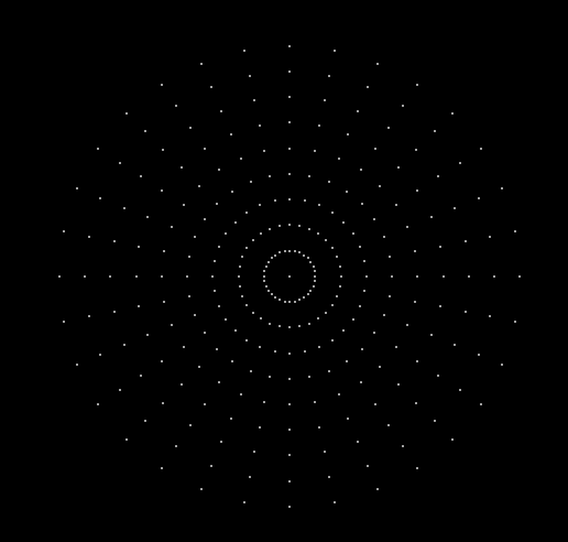
Polar grid
Custom Grid
Custom grid is a special grid type, where you can define custom patterns of how the points are placed in the grid.

Custom grid settings
Pattern X and Pattern Y allow you to define both the number of points and their spacing. The numbers represent the distance, in virtual units, between consecutive points.
For example, using the pattern 3 7 3 will create 4 points: the distance between the first and second point is 3 units, between the second and third point is 7 units, and between the third and fourth point is 3 units.

3 7 3 pattern example
You can also use a pattern multiplier. For example, the pattern 3 4x7 3 will create: the first two points with a distance of 3 units, four points with a distance of 7 units between them, and the last two points with a distance of 3 units.

3 4x7 3 pattern example