 LSS 4
LSS 4Devices and Outputs
The Strip Editor and other tools in the Mapping window are used to draw LED segments. The Devices section is used to locate devices on your local network and assign LED strips to the device outputs.

Devices in mapping window
Ethernet Devices and IP Addresses
Locate Ethernet devices on your network
The first step in device assignment is to find the correct IP addresses of the supported devices (LEC3 or activated Reactivo 2) connected to your network. You can either add the device IP address manually or use the Search button to detect devices automatically.
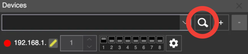
Device search function
When you click the magnifying glass icon, the software will attempt to find all supported devices on your local network. Note that your computer must be on the same IP address range as the devices (default: 192.168.1.x).
macOS Network Configuration (Multiple Interfaces)
When using macOS with both WiFi and Ethernet active at the same time, special network configuration may be required.
If WiFi is used as the Internet source, it must be placed first in the Service Order in macOS Network settings. Otherwise, macOS may attempt to route traffic through the wrong interface.
In addition, the Ethernet adapter connected to the LEC3 device must use a different IP subnet than the active WiFi network.
Example configuration:
- WiFi network:
192.168.1.x - LEC3 Ethernet network:
192.168.2.x
Do not use the same subnet for both interfaces (for example 192.168.1.x on WiFi and 192.168.1.x on Ethernet).
Real-world example
In one case, a LEC3 device was connected via Ethernet on the same subnet (192.168.1.x) as the active WiFi network (192.168.1.x).
The device could not be pinged and did not connect properly. LSS Management behaved inconsistently, with devices repeatedly disappearing and reappearing.
The issue was resolved by configuring the Mac Ethernet interface used for the LEC3 device to a different subnet (for example 192.168.2.x).
Add device manually
If you already know the IP address of your devices, you can add them manually using the + button. Enter the device’s IP address, and after clicking OK, it will be added to the list of devices.
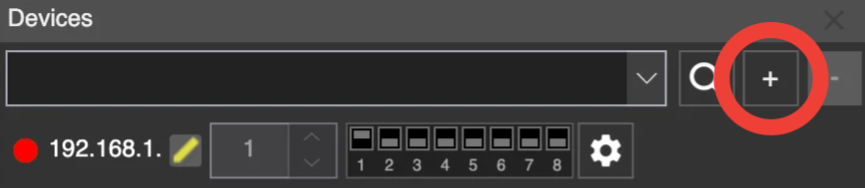
Add device manually
Alternatively, you can click the - button to remove a selected device from the devices list.
Setting the IP address
Once you have added a new device using the + button, you can also change the entire IP address (all 4 numbers), not just the last byte. Use the yellow pencil button next to the IP address.
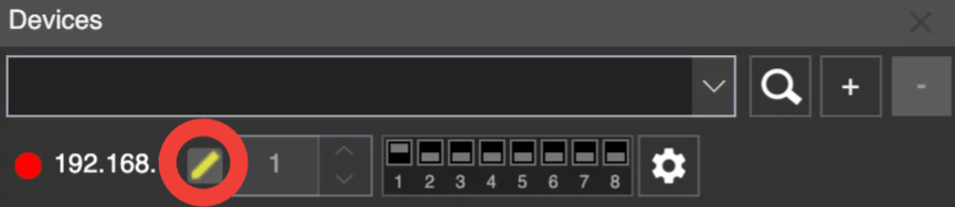
Set device IP address
The following window will appear, allowing you to set all four numbers of the device’s IP address.
You can also use DIP switch control to change the last number of the IP address.
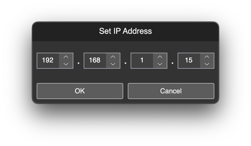
Set all 4 numbers of IP address
Assign LED Strips to Devices
List of LED Strips in Device
After adding a new Ethernet device to the list of devices, there is no LED strip assigned to its outputs.
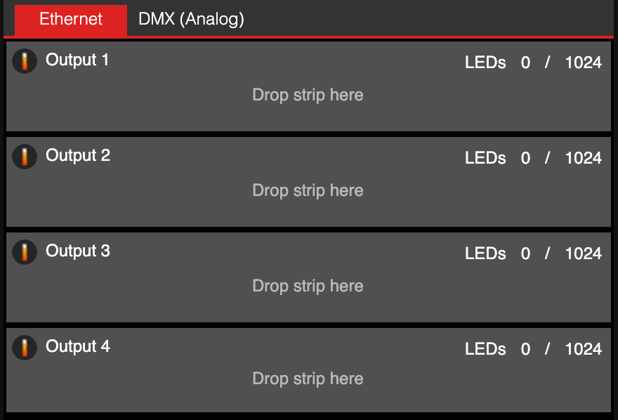
Device with no assigned strip
Assign LED Strip to Device
To assign an LED strip to the output of the device, drag and drop the desired LED strip onto the device’s output.
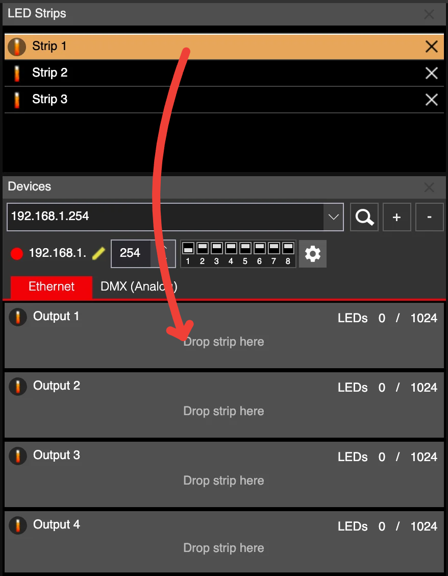
Drag and drop the LED strip to device output
The strip is now assigned to Output 1 of the device.
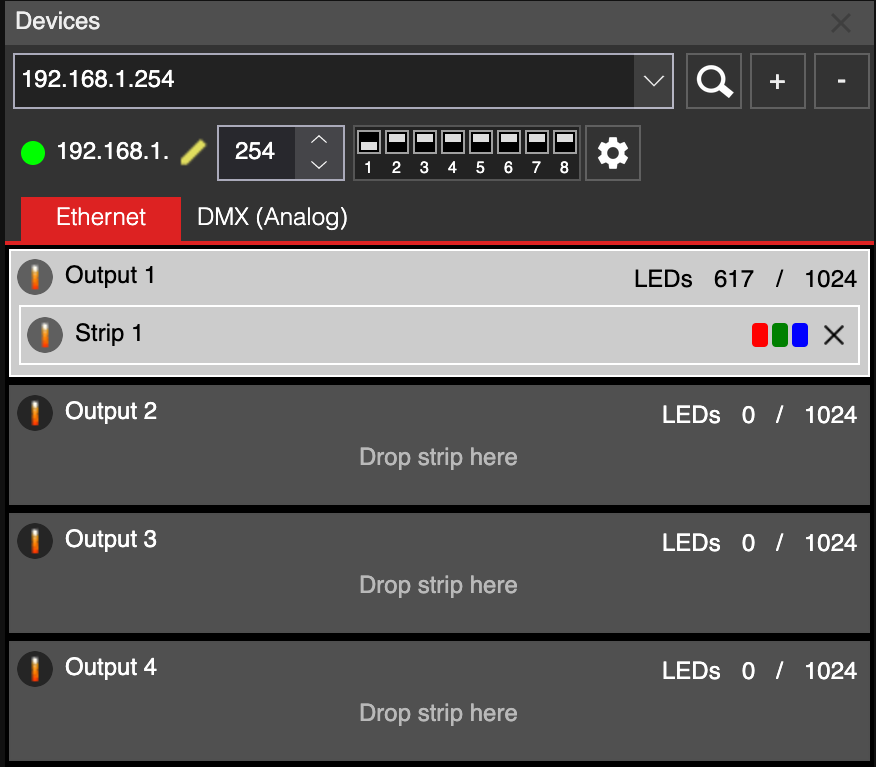
Strip 1 assigned to Output 1
Assign Multiple Strips to Device (Grouping)
There is an interesting feature available in LSS4: you can assign multiple LED strips to device outputs and group them together. This is especially practical if you need to create different LED strip animations for each segment connected to one output of the device. To create a group of two LED strips, simply drag and drop the second LED strip onto Output 1.
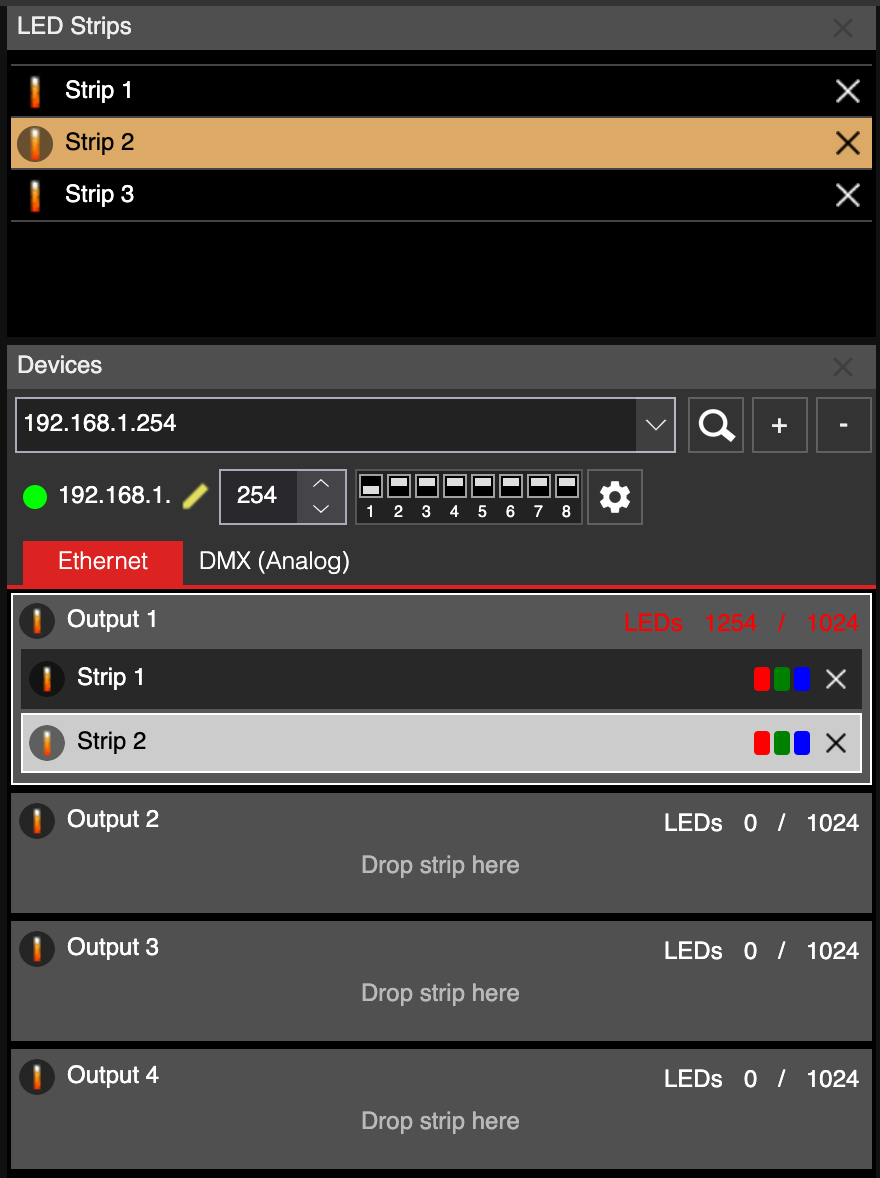
Second LED strip assigned to output 1
Output Properties in Device
Every output of the device in the Devices window contains several settings att the bottom of the window.
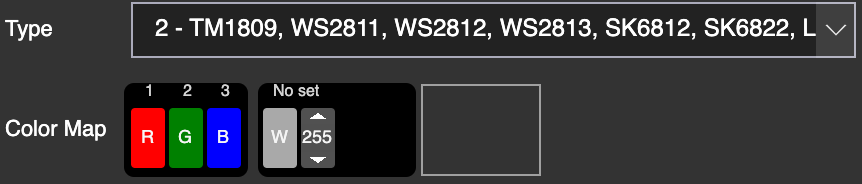
Output settings
In the Type, you can select the used chip (IC) of your pixel LED strip connected to the selected output. In the Color Map, you can change the order of the default RGB channels or even remove or add additional color channels. This is practical for RGBW pixel LED strips.
The number 255 allows you to add a constant instead of a color channel, which is practical for advanced pixel LED strips with additional functions.
Assigned LED Strip Properties in Device.
The LED strip assigned to the device also contains additional properties. In this case, you can simply set the color order of the RGB(W) channels. The reason is simple - you cannot have different types of LED strips (with different ICs) connected to one output.
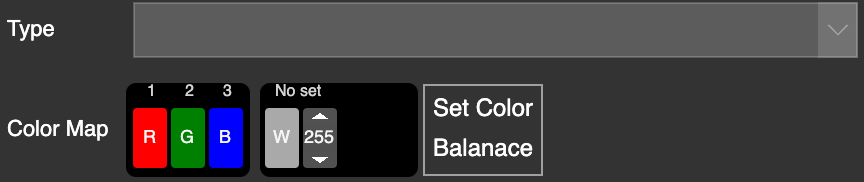
Strip settings in device
For the LED strip assigned to Output, you can set the Color Balance. This allows you to adjust the intensity of each color channel in the standard color.
Color Balance
Color balance allows you to set the intensity of every color channel on the device’s output. A practical example of this is using an RGBW LED strip - you may want to use the 4th white channel as the pure white color when the RGB channels are set to 255, 255, 255. In this case, you can select the W channel in the color cube, set the RGB values to 0, and set the W value to 255. This will prevent the white color from using a “bad” RGB-white color, and instead use the 4th channel as a “nice” white color.
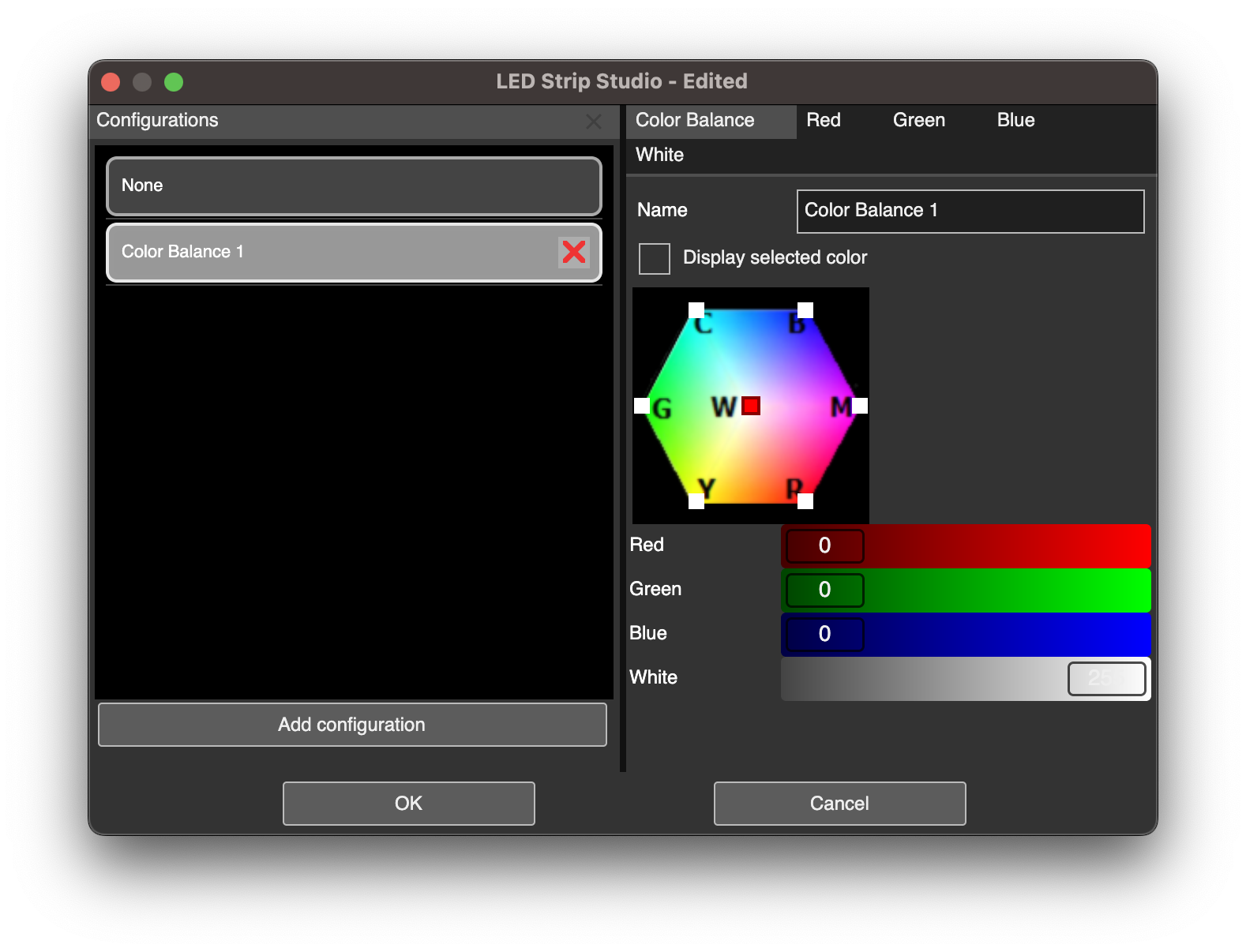
Color balance editing intensity of color channels in W color
In the Red, Green, Blue, and White tabs of the Color Balance window, you can set a fade curve for each of those channels.