 LSS 4
LSS 4Drawing
To draw your first LED segment in LSS4, you first need to create a new digital LED strip. A digital LED strip means that each LED pixel can be controlled individually (also called a pixel LED strip).
In the main menu, select Add Digital. This will create a new pixel LED strip in the LED Strips list.
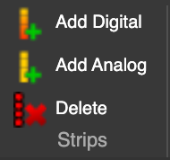
Add Digital strip in the menu
You can also use analog strips in LSS4 (standard RGB or RGBW strips controlled typically by DMX). They can be controlled using DMX output from a LEC3 device. To add a new analog strip, press Add Analog.
LED Strip List
Once you press Add Digital or Add Analog, a new strip will be added to the list of LED Strips. The item in the LED Strips list can be a single LED segment, or a complicated shape made up of several LED segments.
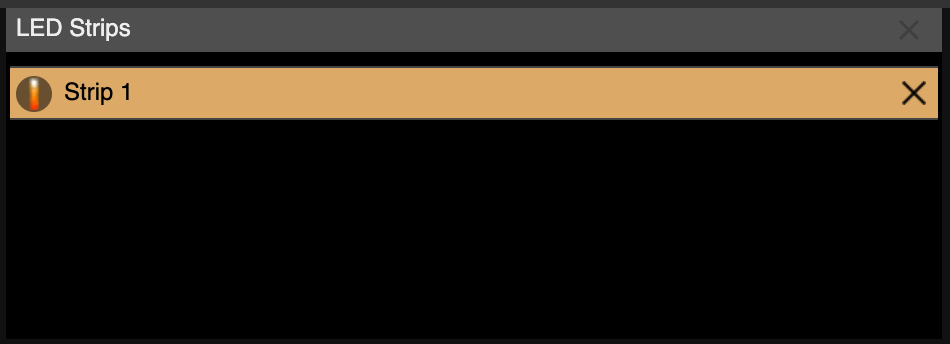
New digital strip in the list of LED strips
Now you can start to draw LED segments of your LED strip. You can use several shapes to draw the LED segments. We can start by the easiest one, which is Points.
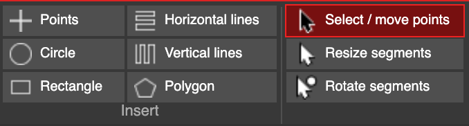
Drawing tools in mapping window
Once you select Points, you can use the Strip Editor area to draw LED segments. Press and hold the left mouse button to draw a straight line, which creates a new LED segment.
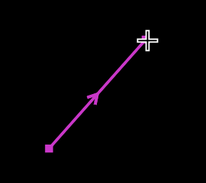
New segment added in the Strip Editor
Once your first segment is drawn, you can continue from any of its endpoints to create a multi-line shape.
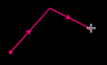
Multiline in strip editor
A multi-line can contain any number of LED segments, but it should always match the actual LED segments installed in your setup. You can also create a split multi-line, which is useful for drawing independent strips that are connected through a single signal line. To draw a split multi-line, click and hold the left mouse button outside the endpoints of any existing segment.
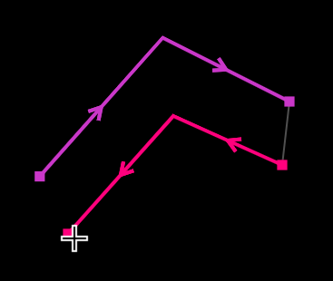
Split multi-lines representing independent strip segments
LED Strip Settings
Every LED segment in the Strip Editor has several settings in the LED Strip Settings section of the mapping window. Most of these settings apply to the entire LED strip. Only the Segment Pixel Count is specific to the selected segment, defining the number of LED pixels for that segment.
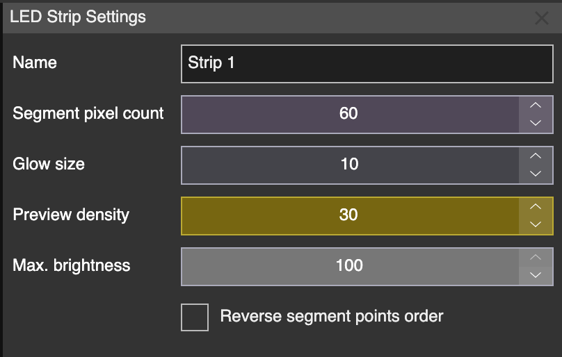
LED Strip Settings
| Setting | Explanation |
|---|---|
| Name | Name of the LED strip (output) in the LED Strips list. |
| Segment Pixel Count | Number of LED pixels in the selected segment. |
| Glow Size | Size of the glow effect in the preview. |
| Preview Density | Density of LED pixels in the preview window. |
| Max. Brightness | Maximum brightness of the entire LED strip. |
All the settings are related to entire LED strip (or split multi-line) except the Segment Pixel Count. This one is set per each individual (non-split) multi-line. In our example, you can e.g. set 10 pixels per first multi-line and 20 pixels per second multi-line.
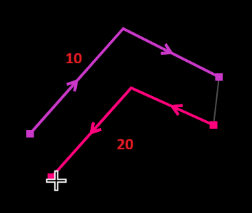
Each multi-line can have a different number of LED pixels.
Drawing tools
In the Insert menu you can use different kinds of drawing tools.
Drawing tools in mapping window
| Tool | Explanation |
|---|---|
| Points | Draw split multi-line segments one by one. |
| Circle | Draw a circle. After drawing, you will be prompted to set the number of pixels for the circle. |
| Rectangle | Draw a rectangle. You will be prompted to set the number of X and Y points. |
| Horizontal Lines | Draw multiple horizontal lines. You will set the number of lines and points per line. The Zig Zag option determines whether the signal connection always starts on the left or alternates in a zig-zag pattern. |
| Vertical Lines | Same as Horizontal Lines, but the lines are arranged vertically. |
| Polygon | Draw a polygon starting from a triangle. You will set the number of lines and pixels per polygon. |
On the right side of the Insert menu, you have additional settings that allow you to manipulate individual points or entire segments.
| Tool | Explanation |
|---|---|
| Select/Move Points | Select and move individual points. You can also convert a straight segment to a curve (and back) or delete points in this mode. |
| Resize Segments | Move and resize entire LED segments. |
| Rotate Segments | Move and rotate entire LED segments. |
Straight, curved or smooth LED segments
You can also create curved LED segments in the mapping window using standard Bezier curves. Each point of a segment can be of type Line, Curved, or Smooth. The type of the selected point is shown in the Curve menu.
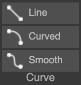
Curved menu
To convert a straight segment into a curve, select its starting point and, in the Curve menu, click Curved. This adds control points that allow you to adjust the curvature of the segment. You can manipulate the control points individually, or left-click the red segment line to move both control points simultaneously.
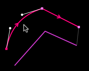
Straight segment converted to curved
The Smooth point type is useful when you need a seamless connection between the previous and next segment.
Tools menu
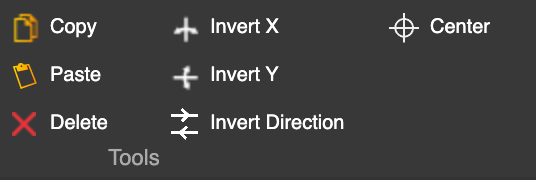
There are several practical commands available in the Tools menu of the mapping window.
Tools menu
| Tool | Explanation |
|---|---|
| Copy | Copy the selected LED segment(s) to the clipboard. |
| Paste | Paste LED segment(s) from the clipboard. Hover over the Strip Editor to preview the curves, and click the left mouse button to place them. |
| Delete | The behavior depends on the drawing mode. In Select/Move Points mode, it deletes selected points. In Resize/Rotate Segments mode, it deletes entire LED segments. |
| Invert X | Flip the selected LED segment(s) horizontally. |
| Invert Y | Flip the selected LED segment(s) vertically. |
| Invert Direction | Invert the signal direction for selected LED segment(s). Useful for adjusting signal flow. |
| Center | Center the selected LED segment(s). |
Highlight color
The Highlight Color is a practical tool that allows you to visualize the selected LED segment(s) on your actual setup. When enabled, the selected segment(s) change to the chosen color, helping you verify the correct order of LED segments and the number of LED pixels in each segment.
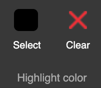
Highlight color menu
In Select, you can choose the color used to highlight the selected segment(s). The Clear option turns off the highlighting function.