Technology
What Is WS2815? 12 V Addressable LED Strip Explained
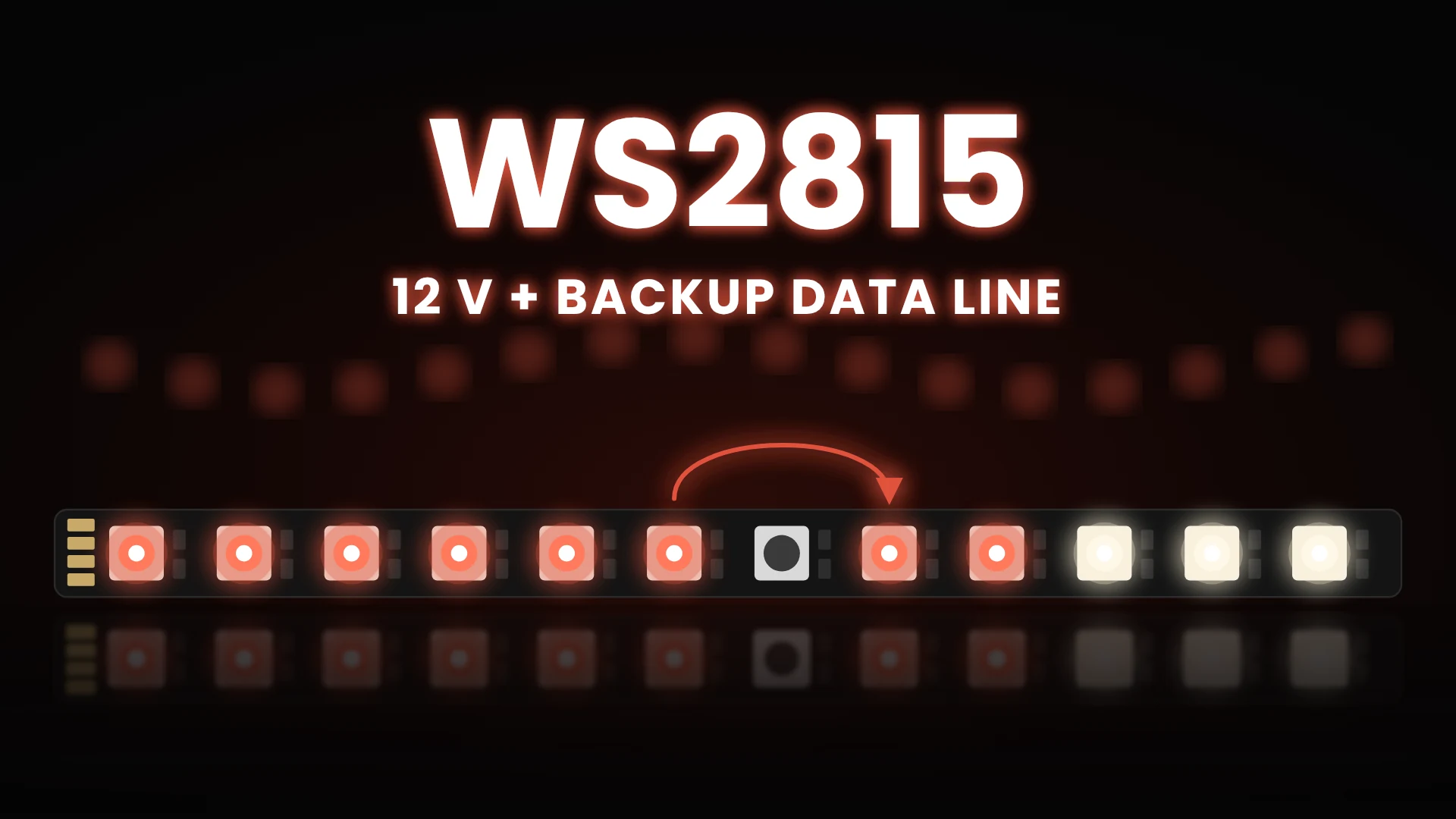
WS2815 is the pixel chip we reach for when a strip has to run long, stay reliable and be hard to reach once it is installed. It looks like a WS2812B, but it runs at 12 V and carries a second data wire that routes the signal around a dead pixel. Those two changes alter how you wire, power and service the whole installation.
This guide explains what the chip is, how the backup data line really works and why 12 V matters. It also covers how many pixels fit on one controller output and how it compares with other 12 V pixel ICs. It is written for integrators, event technicians and lighting designers who specify these strips on real projects. The protocol basics shared with other single-wire chips are covered in our SK6812 guide, so this article focuses on what is different.
What Is WS2815 and Where Is It Used?
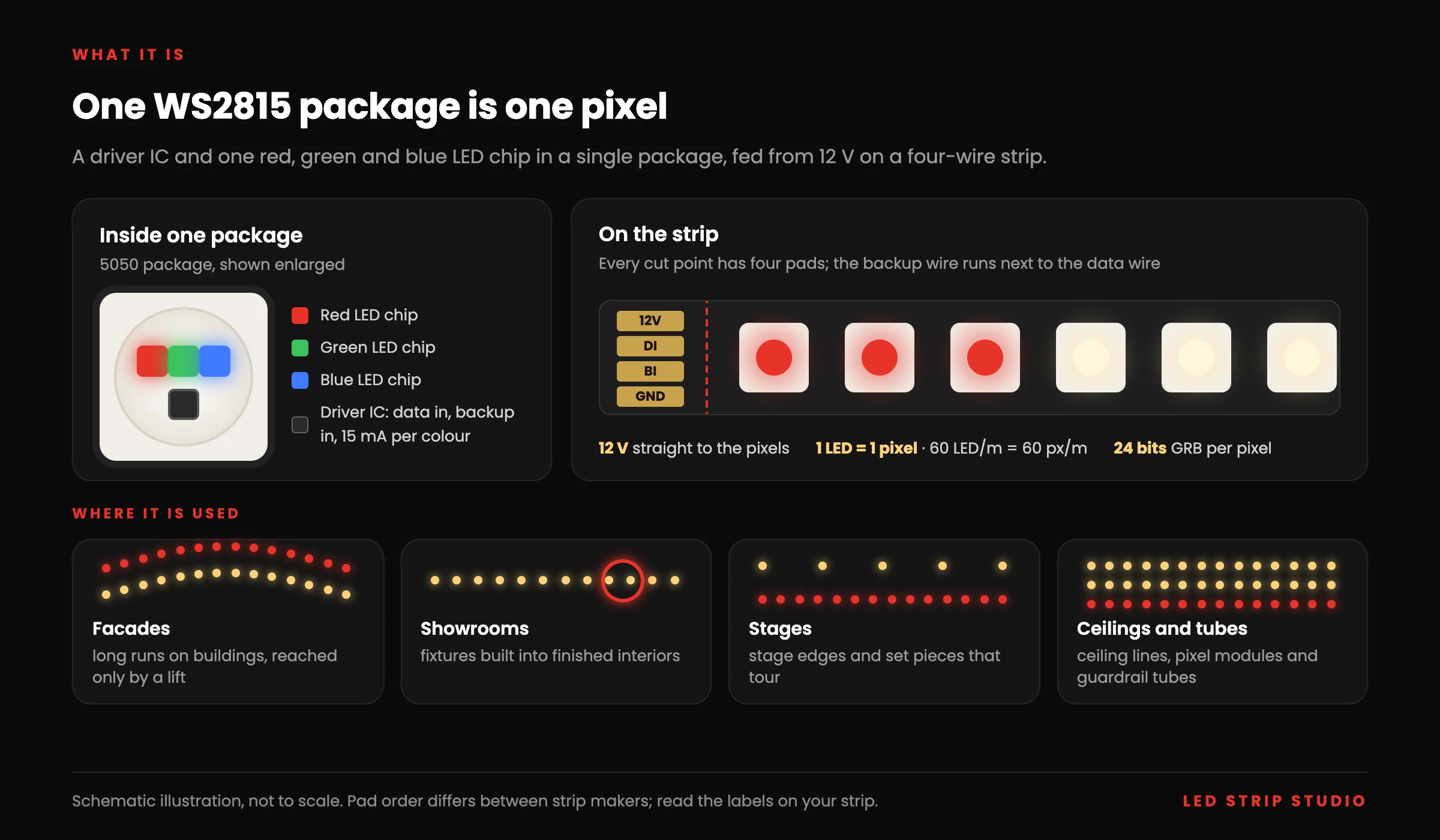
WS2815 is a Worldsemi addressable LED package that combines a driver IC with one red, green and blue LED chip. Each package is one pixel with its own colour, set by 24 bits of data arriving on a single data wire. Unlike most 5 V pixel chips, it runs directly from 12 V and has a second, backup data input.
You find it in flexible strips, rigid bars, pixel modules and guardrail tubes. Typical uses are facades, showrooms, stages and other places where a dark section is expensive to fix. We use 12 V strips as our default in our own projects, and the showroom case study below is one example. The one-LED-per-pixel design means a 60 LED/m strip really has 60 pixels per metre.
Which Packages and Strip Variants Exist?
The name covers several packages with the same protocol and the same backup logic:
- Standard 5050 package — the standard 5 × 5 mm package found on most strips at 30, 60 and 144 pixels per metre.
- WS2815B-MINI (3535) — a smaller package for narrow strips and 96 pixels per metre.
- WS2815B-2121 and -4020 — tiny and side-emitting packages for dense or edge-lit designs.
- 24 V strip versions — a DC/DC converter on the strip feeds the 12 V pixels, for example 66 pixels per metre with a cut point every 6 pixels.
Never connect 24 V to a standard strip. The absolute maximum supply of the chip is 13.5 V, so a 24 V feed destroys it immediately.
What Are the Key WS2815 Specifications?
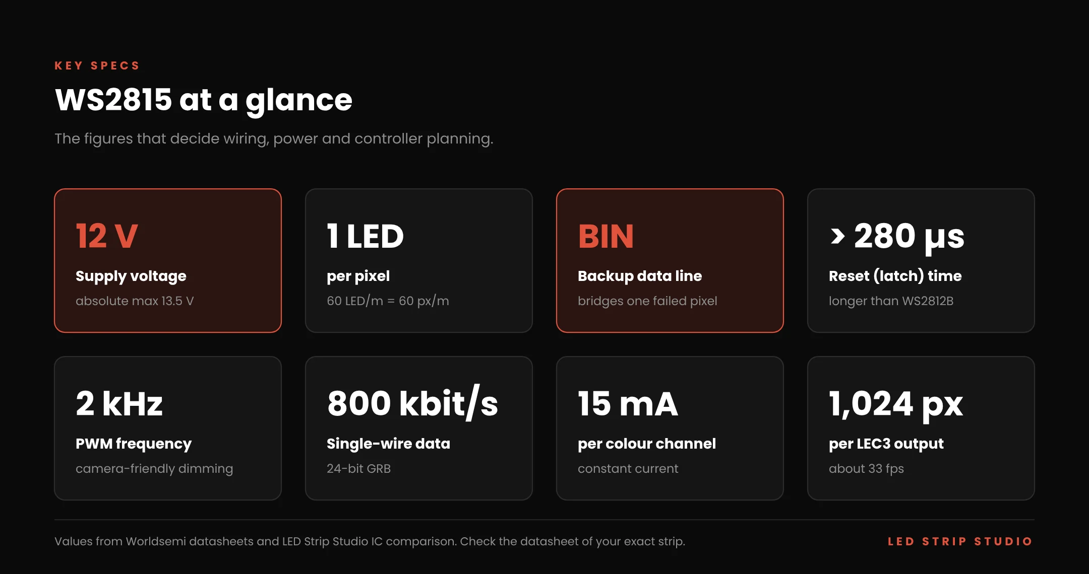
The table collects the figures that matter when you plan an installation. Values come from Worldsemi datasheets and our internal comparison of the ICs our controllers support. Revisions differ slightly, so check the datasheet of the exact strip you buy.
| Parameter | WS2815 value |
|---|---|
| Supply voltage | 12 V DC (absolute maximum 9.5–13.5 V) |
| LEDs per pixel | 1 RGB LED |
| Data protocol | Single wire, 800 kbit/s, 24-bit GRB, MSB first |
| Resolution | 8 bits per colour, 256 levels |
| Backup data line | Yes (BIN / BO) |
| Reset (latch) time | > 280 µs |
| PWM frequency | 2 kHz |
| Constant current per channel | 15 mA (some B revisions 10 mA) |
| Signal distance between two pixels | > 3–5 m, depending on revision |
| Cascade length in datasheet | ≥ 1,024 pixels at 30 fps |
| Wires on the strip | 4: 12V, DI, BI, GND |
| Pixels per output (LEC3, SPI Matrix) | 1,024 |
How Does the Protocol Differ From SK6812 and WS2812B?
The bit encoding is the same family: 800 kbit/s, one bit every 1.25 µs, with the length of the high pulse setting 0 or 1. We explain that timing in detail in how bits are encoded at 800 kHz. The data order is GRB, as on WS2812B.
The practical difference is the reset. This chip needs the data line held low for more than 280 µs before it latches a frame. Older WS2812B code often uses 50–80 µs, which is too short, so frames are not latched reliably and the strip flickers or freezes. On a pixel controller, select WS2815 as the chip type rather than a generic WS2812B profile.
Why Does 2 kHz PWM Matter on Camera?
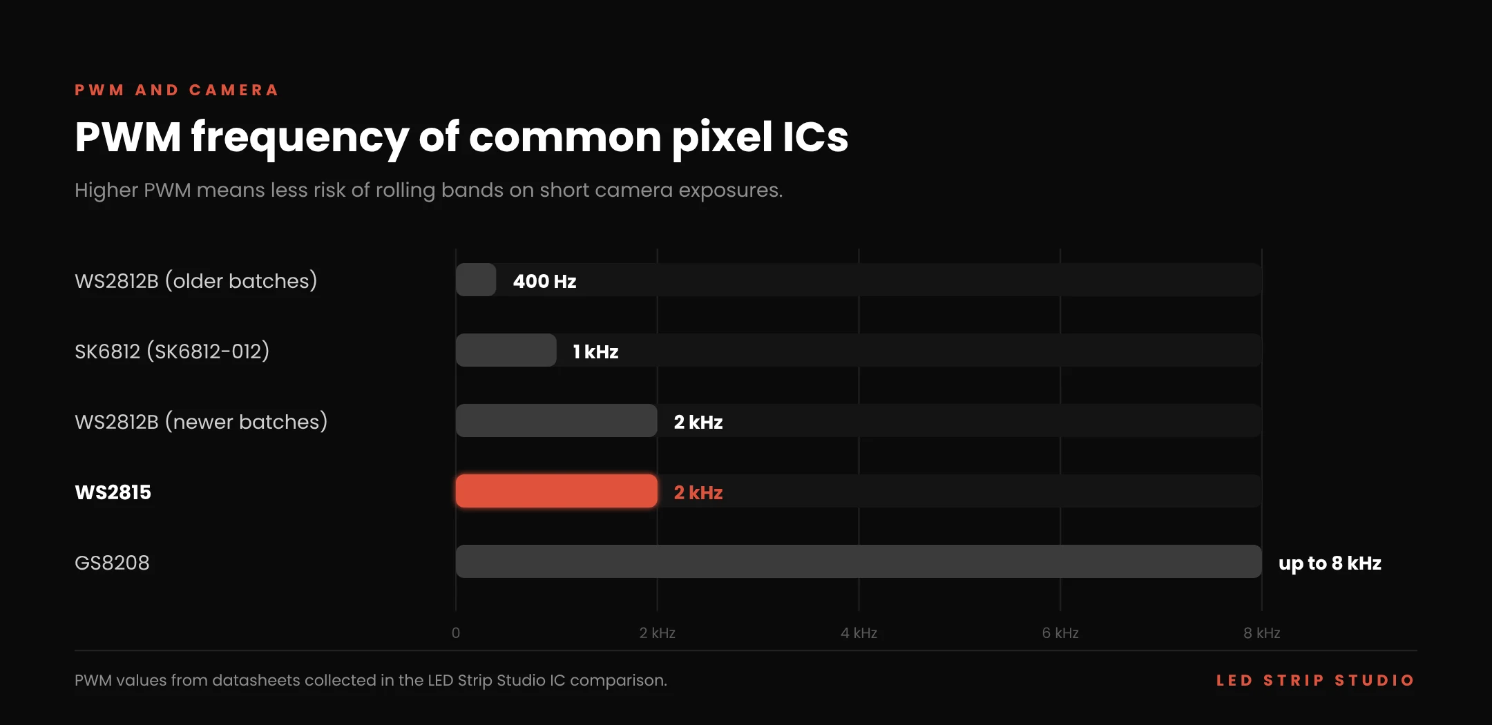
PWM frequency is how fast each LED switches on and off to create dimmed levels. Cameras with short exposure times can catch that switching as rolling bands or flicker. Here the PWM runs at 2 kHz, compared with 1 kHz on the SK6812-012 revision and 400 Hz on older WS2812B batches.
That makes it a sound default for venues that are also filmed or streamed. For broadcast studios with high-speed cameras, ICs such as GS8208 with up to 8 kHz go further. Our article on pixel LED for TV studios covers camera-safe pixel lighting in more detail.
How Does the WS2815 Backup Data Line Work?
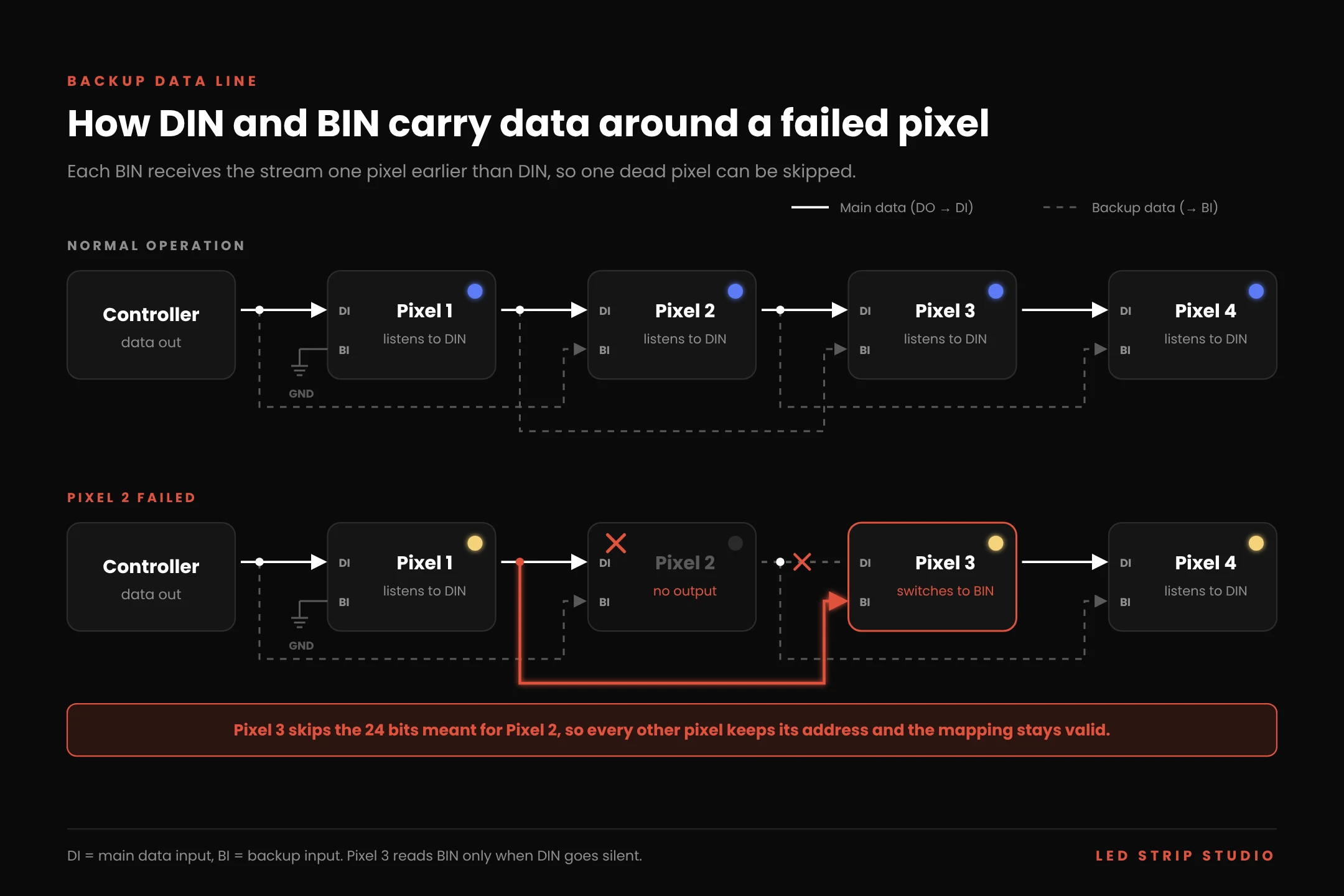
The backup line is a second input that receives the data stream one pixel earlier than the main input. Each pixel has a main input (DIN) and a backup input (BIN). On the strip, BIN of each pixel is wired to the data that entered the previous pixel, so it carries the stream before that pixel took its share.
In normal operation the pixel listens to DIN and only compares it with BIN. If DIN stops receiving data, the pixel switches to BIN and skips the 24 bits meant for the dead neighbour. Every other pixel keeps its address, so the mapping in your software stays valid. According to the datasheet, the pixel then stays on BIN until the power is switched off.
What Happens When One or Two Pixels Fail?
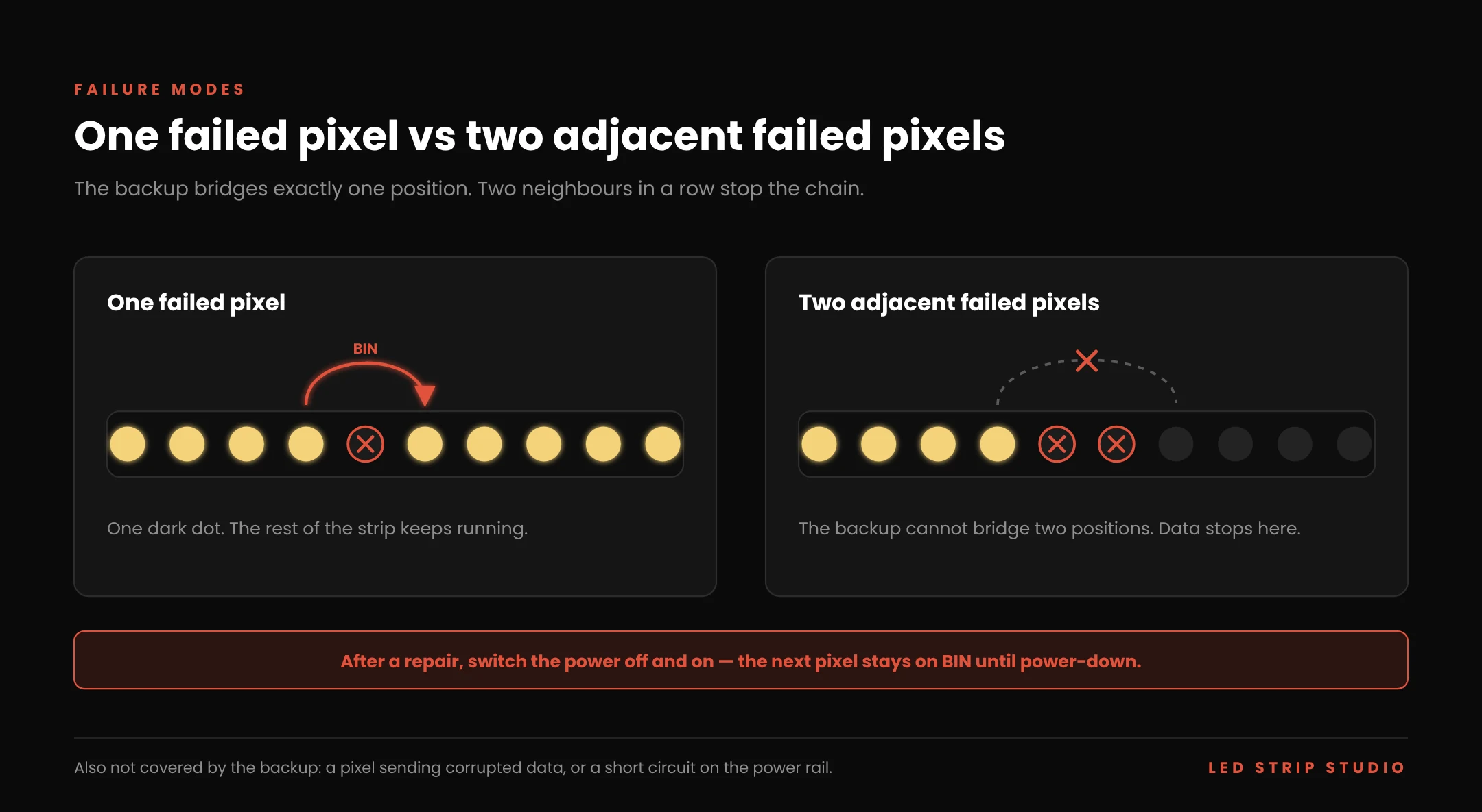
One failed pixel stays dark, and the rest of the strip keeps running. The pixel after it picks up the stream from BIN and nobody in the audience notices a moving fault. That is the main reason to specify a backup-line IC for facades and ceilings that need a lift to reach.
Two adjacent failed pixels stop the chain, because the backup only bridges one position. The backup also cannot help when a pixel still sends data, but sends it corrupted. It also cannot help when a short circuit pulls down the power rail. After you replace a pixel, switch the power off and on, or the next pixel stays on the backup input.
How Should You Wire the BI Input?
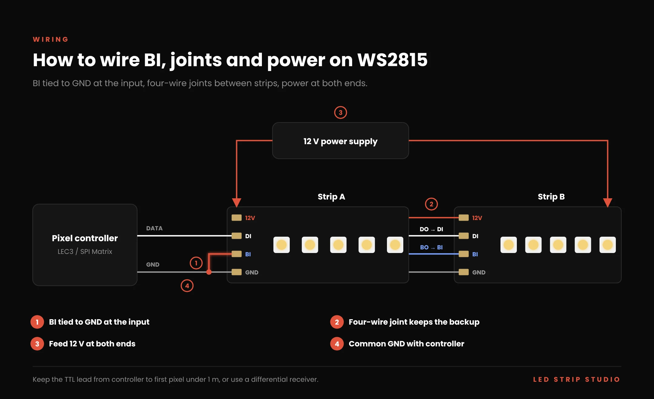
At the start of the strip there is no previous pixel, so the BI wire needs a defined state. The usual practice is to tie BI to GND at the input connector. The first pixel then always takes data from DI and never mistakes noise for data.
Some installers feed the controller data to both DI and BI instead, which adds redundancy for the first pixel. Either way, never leave a long BI lead floating, because it acts as an antenna. Between two strips, connect DO to DI and BO to BI with four wires. A three-wire joint works, but it removes the backup across that joint.
Why Does WS2815 Run at 12 V Instead of 5 V?
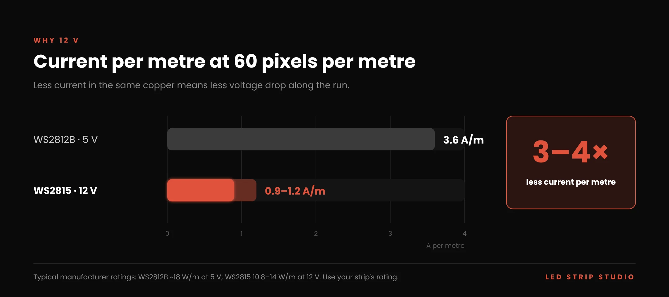
Because the current, not the voltage, causes the drop along a strip. Each colour channel is driven at a constant 15 mA, and strip makers rate these strips at 60 pixels per metre at roughly 10.8–14 W/m. At 12 V that is about 0.9–1.2 A per metre. A 5 V WS2812B strip with the same density is typically rated around 18 W/m, which is 3.6 A per metre.
Three to four times less current means three to four times less voltage loss in the same copper. The remaining loss is also a smaller share of 12 V than of 5 V. The result is a run that keeps its colour further from the feed point.
Other 12 V pixel strips often get there by driving three LEDs from one IC, so 60 LED/m becomes 20 pixels per metre. This chip keeps one pixel per LED at 12 V. You get the wiring advantages of 12 V without giving up resolution.
Where Should You Inject Power?
Feed every run at both ends as a baseline, and add an injection point in the middle of long runs. Strip makers rate a 5 m reel for feeding from one end. Our default for permanent installations is still to feed at both ends, because it halves the current in the copper.
Tie the controller GND to the strip GND at the start of every run. The data and the backup signal are both referenced to GND, so a missing common ground causes random colours that look like a data fault. An aluminium profile with a diffuser also helps here, because it carries heat away from the strip.
How Do You Size the Power Supply?
Take the rated W/m of the exact strip and multiply it by the length on each supply. A 15 m run at 14 W/m needs 210 W, which is 17.5 A at 12 V. With a 20 % reserve, a 250 W supply per run is a sensible choice.
Real content rarely runs at full white, but the supply must survive the moment it does. Power cabling and soldering are where most labour goes, as our breakdown of what a pixel LED installation really costs shows.
How Many WS2815 Pixels Can One Output Drive?
One output of an LEC3 pixel controller for WS2815 or an SPI Matrix drives up to 1,024 pixels. At that load the output refreshes at about 33 frames per second. With four outputs, one unit drives 4,096 of these pixels.
The longer reset hardly changes that figure. A full output carries 24,576 bits, which takes about 30 ms on the wire. The 280 µs reset adds only 0.2 ms more than SK6812 needs, so the frame rate stays practically the same.
How Long Can One Run Be per Output?
The pixel limit turns into a maximum run length per output. The table also shows how many standard 5 m reels that is.
| Pixel density | Pixels per 5 m reel | Max run per output (1,024 px) | Reels per output |
|---|---|---|---|
| 30 px/m | 150 | 34.1 m | 6.8 |
| 60 px/m | 300 | 17.0 m | 3.4 |
| 96 px/m | 480 | 10.6 m | 2.1 |
| 144 px/m | 720 | 7.1 m | 1.4 |
These are data limits. Power still has to be fed as described above, and a run of 17 m at 60 px/m needs more than one feed point.
How Many Art-Net Universes Does a Run Need?
One Art-Net universe holds 170 RGB pixels, because each pixel uses 3 of its 512 channels. A full output of 1,024 pixels needs 7 universes, while 1,020 pixels fit into 6. Our Art-Net universe calculator does that rounding per output.
How Does WS2815 Compare to Other Pixel ICs?
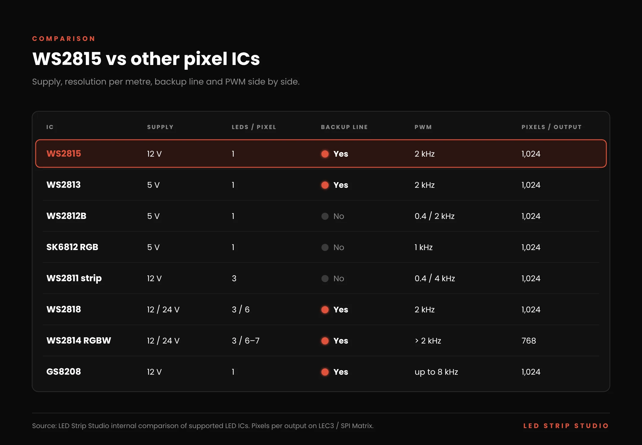
The table compares the chip with the pixel ICs it is most often weighed against. It is based on our internal comparison of the chips our controllers support.
| IC | Supply | LEDs per pixel | Backup line | PWM | Pixels per output |
|---|---|---|---|---|---|
| WS2815 | 12 V | 1 | Yes | 2 kHz | 1,024 |
| WS2813 | 5 V | 1 | Yes | 2 kHz | 1,024 |
| WS2812B | 5 V | 1 | No | 400 Hz (older) / 2 kHz (newer) | 1,024 |
| SK6812 RGB | 5 V | 1 | No | 1 kHz | 1,024 |
| WS2811 strip | 12 V | 3 | No | 400 Hz (older) / 4 kHz (newer) | 1,024 |
| WS2818 | 12 / 24 V | 3 / 6 | Yes | 2 kHz | 1,024 |
| WS2814 RGBW | 12 / 24 V | 3 / 6–7 | Yes | > 2 kHz | 768 |
| GS8208 | 12 V | 1 | Yes | up to 8 kHz | 1,024 |
When Is WS2815 the Right Choice?
Choose it when the strip is long, hard to reach or expected to run for years. Facades, showroom fixtures, stage edges and ceilings fit that profile. It is also a good fit for filmed venues thanks to its 2 kHz PWM.
Choose something else when the brief needs a real white channel. Then look at SK6812 RGBW, or WS2814 if you also want a backup line. Very dense 5 V matrices and small DIY builds are often fine with WS2812B. For the highest camera demands, a 12-bit IC such as GS8208 is worth testing.
Example: How Was WS2815 Used in a Showroom?
The Macho & Chlapovic numismatic showroom carries circular openings in its inner facade, each one a stylised coin. Every ring is a WS2815 strip at 60 pixels per metre, running at 12 V. The controller could not sit near the rings, so SPI Lamp units take the signal to each fixture over CAT6. The full story is in our pixel LED showroom case study.
The rings sit inside a finished facade, so every repair would mean opening the decoration. That is exactly where the backup line pays off: a single failed pixel leaves one dark dot, not a dark coin. The client changes scenes daily from the LSS Remote app.

For larger runs, the planning follows the same arithmetic. Take a 30 m stage edge at 60 px/m as a modelled example:
| Item | Value |
|---|---|
| Strip | WS2815, 12 V, 60 px/m |
| Total length and pixels | 30 m, 1,800 px |
| Outputs used | 2 × 900 px (limit 1,024) |
| Refresh rate per output | ~37 fps |
| Art-Net universes | 12 (6 per output) |
| Controller | 1 × LEC3 or SPI Matrix, STANDARD tier |
| Power | 2 × 15 m runs, each fed at both ends; ~250 W supply per run at 14 W/m |
| Joints | Four-wire DO→DI and BO→BI; BI tied to GND at each run input |
The STANDARD tier covers 12 universes and 2,048 pixels, which fits 1,800 pixels with reserve. The differences between LITE, STANDARD and PRO are explained in a separate article.
How Do You Wire and Control WS2815 Step by Step?
For a prototype, an ESP32 with WLED or a NeoPixel-style library can drive these strips, as long as the reset is long enough. For an installation with several outputs, mapping and remote control, a dedicated pixel controller does the job. The controller only sends one data line; the backup routing happens on the strip itself.
Which Controller Suits a 12 V Pixel Strip?
LEC3 and SPI Matrix both support the chip and set the chip type per output in their web configuration. LEC3 plays shows from its SD card without a PC, while SPI Matrix receives Art-Net from a console or media server. Reactivo 2 covers smaller wireless installations.
Content is built in LED Strip Studio 4 and stored on the controller. Standalone playback from an SD card keeps the installation running after the laptop leaves. The full list of chips is on our supported LED IC page.
How Far Can the Data Signal Travel?
The datasheet quotes 3–5 m between two pixels, but that is a short pixel-to-pixel link. From a controller to the first pixel we recommend less than 1 m of plain TTL cable. Beyond that, cable capacitance rounds off the pulses until bits are misread.
For longer feeds, convert the signal to differential. The Symmetrizer carries it over twisted pair, and SPI Lamp 2 carries it 100 m over Cat5e. Only the main data line travels; tie BI to GND at the receiving end. Our guide to sending an SPI signal over long distance has the full calculation.
What Are the Setup Steps?
- Confirm the IC, the supply voltage (12 V or a 24 V strip with converter) and the pixels per metre.
- Split the installation into runs of up to 1,024 pixels per output.
- Place the controller within 1 m of each run start, or add a differential receiver.
- Wire DI to the controller data and BI to GND at each run input; use four-wire joints between strips.
- Feed 12 V at both ends of each run and connect a common GND.
- Set the matching chip type for each output, save the outputs and create the pixel mapping.
- Test solid red, green, blue and white, then export the scenes to the SD card and test a power cycle.
The solid-colour test catches wiring faults in seconds. Swapped red and green mean a wrong colour order. Flicker on a static colour usually means a reset that is too short or a missing common GND.
Which WS2815 Mistakes Cost the Most?
Most faults we see on these strips come from wiring and configuration, not from broken LEDs.
- Using a WS2812B profile with a short reset. Frames are not latched reliably; select the correct chip type so the reset exceeds 280 µs.
- Connecting 24 V to a standard strip. The chip is rated to 13.5 V; only strips with an on-board converter accept 24 V.
- Leaving a long BI lead floating. Tie BI to GND at the input so noise cannot be read as data.
- Joining strips with three wires. The strip still works, but the backup no longer covers the joint.
- Expecting the backup to cover everything. Two adjacent dead pixels, corrupted data or a shorted rail still stop the chain.
- Skipping the power cycle after a repair. The next pixel stays on its backup input until the power goes off.
- Missing common GND. Data and backup lines lose their reference, and colours turn random.
Planning a long or hard-to-reach pixel installation? Book a free consultation with our team.
Frequently Asked Questions
Is WS2815 the same as WS2812B?
No. Both use 800 kbit/s single-wire data in GRB order, but this chip runs at 12 V, adds a backup data line and needs a reset longer than 280 µs.
Can a WS2812B controller drive WS2815?
Usually yes, if the controller holds the reset for more than 280 µs. On LEC3 and SPI Matrix, select WS2815 as the chip type for the output.
Do I have to connect the BI wire?
The strip runs without it, but the input end should not float. Tie BI to GND at the input and connect BO to BI at every joint to keep the backup working.
What happens if two pixels next to each other fail?
The data stops after them, because the backup only bridges one pixel. A single failed pixel stays dark while the rest of the strip keeps running.
How much power does a WS2815 strip draw?
Strip makers rate 60 px/m strips at roughly 10.8–14 W/m, which is about 0.9–1.2 A per metre at 12 V. Always size the supply from the rating of your exact strip.
Is WS2815 suitable for filming?
Its 2 kHz PWM is better than most 5 V pixel chips and works for most streamed and filmed venues. For high-speed broadcast cameras, test it on camera or consider a higher-frequency IC.
Summary
WS2815 is a 12 V addressable RGB pixel with one LED per pixel, 8 bits per colour and 800 kbit/s single-wire data. Its backup data line bridges one failed pixel, while two adjacent failures still stop the chain. At 12 V it draws three to four times less current per metre than a 5 V strip, so runs keep their colour further from the feed. One LEC3 or SPI Matrix output drives 1,024 pixels at about 33 fps, and the 280 µs reset must be respected. Tie BI to GND at the input, use four-wire joints and feed every run at both ends.
Sources & references
- Worldsemi — WS2815 datasheet: 12 V, 800 kbit/s, GRB, 2 kHz PWM, reset > 280 µs, 15 mA per channel, > 5 m between pixels, ≥ 1,024 pixels at 30 fps, BIN backup logic
- Worldsemi — WS2815 specification, earlier revision: dual-signal wires, > 3 m between pixels
- Worldsemi — WS2815B and WS2815B-MINI datasheets: 10 mA B revision, 3535 package
- LED Strip Studio — internal comparison of supported LED ICs: pixels per output, PWM, supply variants, backup lines, LEDs per pixel
- LED Strip Studio — Supported LED chips
- Strip manufacturer ratings for 60 px/m WS2815 strips: 10.8 W/m (Derun DR-WS2815FX60-12V), 14 W/m (Contest SMARTTAPE6020-12-WS2815)
- Suntech — ST-WS2815-4PIN-RGB-66-12/24V strip specification: on-board DC/DC converter, cut every 6 pixels
- LED Strip Studio — What Is SK6812?, How Do You Send an SPI Signal Over Long Distance?, Pixel LED Showroom Lighting