Technology
How Does PSL2 Setup Work From Unboxing to First Light?
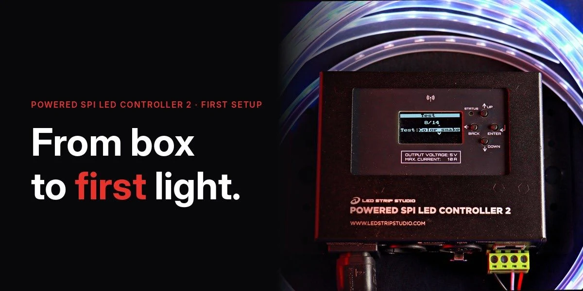
The Powered SPI LED Controller 2 (PSL2) is a pixel LED controller with the power supply built in. There is no separate power brick and no extra wiring between supply and controller. This guide covers the PSL2 setup from a closed box to the first glowing strip, the same steps as in our unboxing video.
It is written for installers and integrators who get a PSL2 on their bench for the first time. You will learn what is in the package, how to read the voltage variant, what each connector does and how to run a test pattern. Once the strip lights up, our guide to PSL2 control options helps you choose how to run it.

What Is PSL2 and What Comes in the Box?
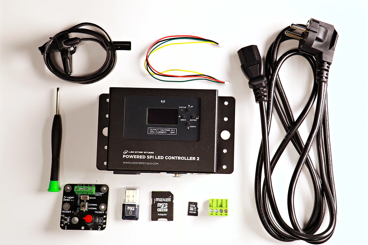
PSL2 is an industrial pixel LED controller with an integrated power supply that drives up to 1,024 RGB or 768 RGBW pixels. Everything you need for the first test ships in the box. The manual lists the controller, the IEC power cable, the LED output plug, the micro SD card, an SD adapter and a USB card reader. Our unit also came with the extras in the lower rows.
| Item | What it is for |
|---|---|
| PSL2 controller | Controller and power supply in one case |
| IEC power cable | Mains to the C14 power inlet |
| LED output plug | 4-pole terminal for the strip (−, CLK, DAT, +) |
| Micro SD card | Stores your animations (FAT32, up to 32 GB) |
| SD adapter and USB card reader | Copy animations from a computer to the card |
| Quickstart guide | The first steps on paper |
| Ethernet and trigger cables | Network and trigger wiring |
| Screwdriver | Tightens the terminal screws |
| Testing trigger board | Tries the trigger input without your own button |
Which PSL2 Power Variant Do You Have?
Check the label on top of the case first. PSL2 comes in 5 V, 12 V and 24 V versions, and your LED strip must use the same voltage. A 5 V strip on a 24 V unit is damaged the moment you power it up.
The input side is the same on every variant: 86–264 V AC at 47–63 Hz, so one unit works on mains almost anywhere. The controller itself uses about 5 W, and the input label on the connector panel states Pmax 100 W.
How Much Power Does Each Variant Deliver?
Output power is voltage times current, and the three variants end up close to each other. Higher voltage means lower current for the same power, which matters for cable cross-section and voltage drop along the strip.
| Variant | Output voltage | Max. current | Output power (V × A) |
|---|---|---|---|
| PSL2 5 V | 5 V | 10 A | 50 W |
| PSL2 12 V | 12 V | 5 A | 60 W |
| PSL2 24 V | 24 V | 2.5 A | 60 W |
The 12 V and 24 V units deliver the same 60 W. The 24 V unit does it with half the current, 2.5 A instead of 5 A. The strip must match the voltage, and its total power must not exceed the rating.
Take a common 12 V WS2815 RGB strip with 60 pixels and 8.64 W per metre. The signal handles 1,024 pixels, which is about 17 m of this strip. The 60 W supply powers 60 ÷ 8.64 = 6.9 m. So one 12 V PSL2 drives 6.9 m on its own, or the full 17 m with an external supply. We cover that wiring in the next episode.
What Do the PSL2 Connectors Do?
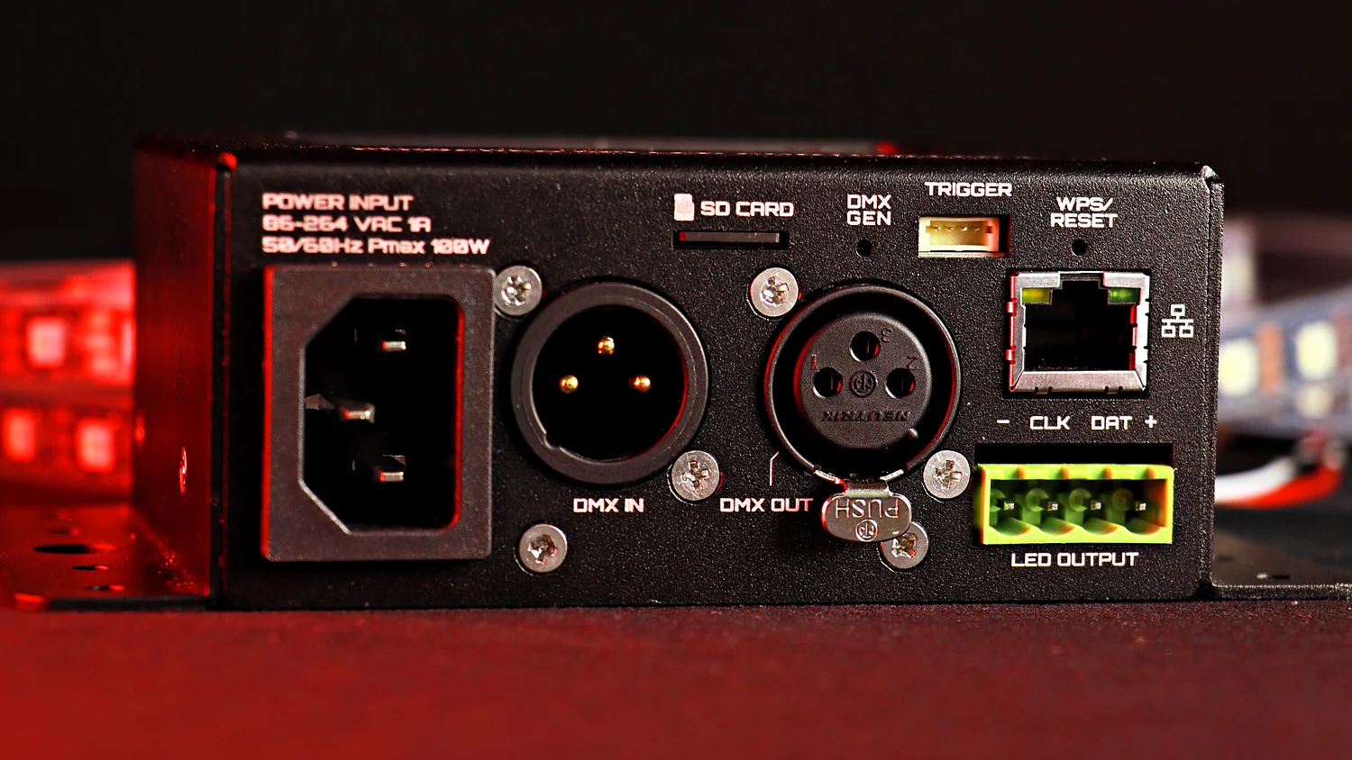
All connections sit on one panel, so a PSL2 setup needs access to one side of the case only. From left to right:
- Power input: IEC C14 inlet for the mains cable, 86–264 V AC.
- DMX IN and DMX OUT: 3-pin XLR, male in and female out. DMX OUT passes the signal through or sends DMX that PSL2 generates; the blue DMX GEN LED shows the second mode. See our page on DMX512 input and output.
- SD card slot: push-push slot for the micro SD card with your animations.
- Trigger: one 4-pin connector with two trigger inputs for buttons, switches or sensors.
- WPS/Reset: recessed button, pressed with a paper clip. A short press starts WPS, 3–10 seconds resets the Wi-Fi credentials, over 10 seconds resets all settings.
- Ethernet (RJ45): 10/100 Mbps network port. Once a wired connection is active, PSL2 switches its Wi-Fi off.
- LED output: 4-pole terminal with GND, Clock, Data and +power.
How Do You Power Up PSL2 for the First Time?
Connect the strip with the unit switched off, insert the SD card, then plug in the mains cable. The manual is clear on the order: establish all connections when the unit is switched off. The first power-up then takes under a minute.
What Does the Start Screen Show?
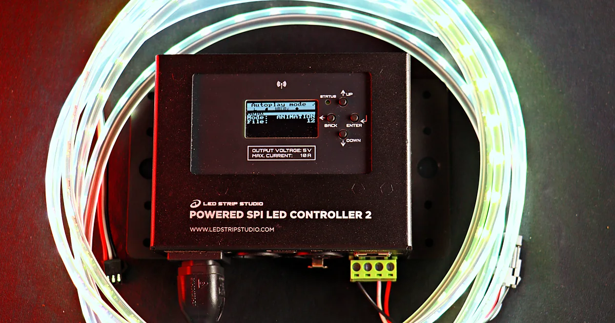
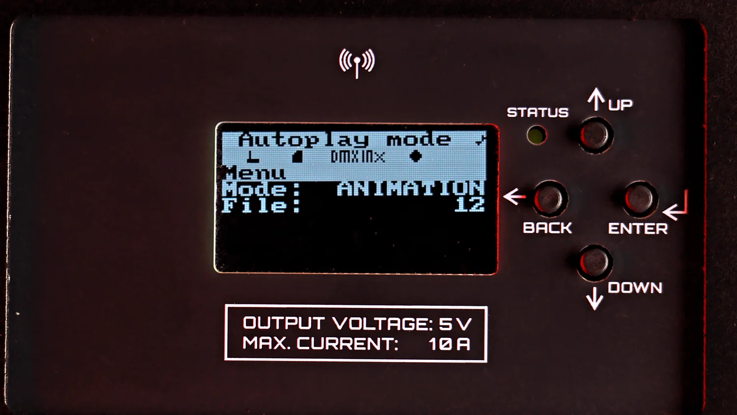
The start screen shows an animated logo and the firmware version. Note the version before you call support, because menus and features depend on it. On our unit it read 6.4.00.
What Does the Display Tell You?
Four buttons (Up, Down, Back and Enter) run the whole menu, and arrows on screen show what each button does. The status bar shows icons for network, SD card, DMX input and data output. A fifth icon appears only when you have unsaved settings. Look there first when something does not work.
When you close the menu after a change, PSL2 asks whether to save it. Answer yes, or the change is not kept. The menu also closes by itself after 60 seconds without a button press.
How Do You Run a Test Pattern?
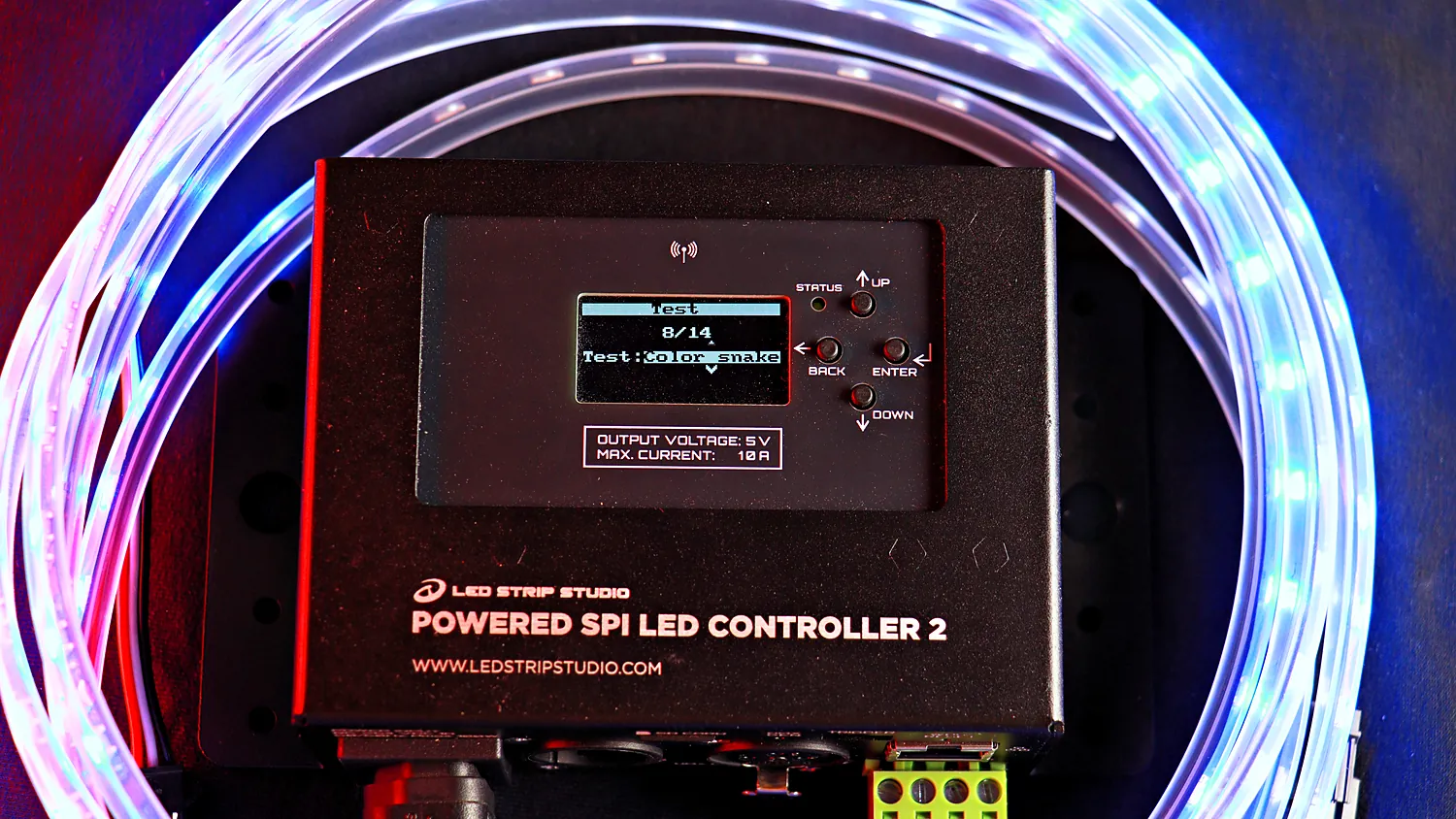
Open Menu, then Test, and pick a pattern. Our unit offered 14 test patterns, from a colour snake to solid white. Test always sends the maximum pixel count for the selected IC type, so the whole strip should light up evenly.
If the strip stays dark or flickers, check the IC type under Menu → Output → IC. If it lights up but red shows as green, change the colour order (Col.Order) in the same menu. Our page about supported LED chips lists the compatible chip families. Test has the highest priority of all control modes, so stop it before you move on.
How and Where Should You Mount PSL2?
Mount PSL2 indoors, in a dry and ventilated place away from heat sources and direct sunlight. The aluminium case is rated IP30 and works from −10 °C to 45 °C. The side tabs take screws, cable ties, clamps or a safety wire.
Keep the middle of the case clear. The Wi-Fi antenna sits almost in the centre, and the manual says not to cover it with conductive materials or cables while Wi-Fi is on.
Which PSL2 Setup Mistakes Should You Avoid?
Most first-day problems with a new controller come from the setup, not from the hardware. These are the ones we see most often:
- Strip voltage that does not match the label. Check the variant before you connect the strip.
- Wiring with the power on. Make every connection with the unit switched off.
- Not saving changes. Answer yes when PSL2 asks, or the change is not kept.
- Mixing up IC type and colour order. A dark strip points to the IC type, swapped colours to the colour order.
- Holding WPS/Reset too long. Over 10 seconds resets all settings, not only Wi-Fi.
- Metal or cables over the Wi-Fi antenna. Leave the middle of the case uncovered.
What Comes After the First PSL2 Setup?
Choose how you will control the installation. Once the test pattern runs, PSL2 can play animations from the SD card, take commands from a phone or a DMX console, or receive live pixel data over Art-Net. Our PSL2 control options guide compares all seven methods.
If the installation should run without a computer on site, read how SD card standalone playback works. The next video in the series covers wiring LED strips and how many metres PSL2 can power. Planning something bigger? Book a free consultation.
Powered SPI LED Controller 2
Pixel LED controller with a built-in power supply, up to 1,024 RGB pixels.
Summary
PSL2 setup takes a few minutes and no computer. The box holds the controller, an IEC power cable, a micro SD card with an adapter and USB card reader and the 4-pole LED output plug. PSL2 comes in 5 V / 10 A, 12 V / 5 A and 24 V / 2.5 A variants, so the strip voltage must match the label. The input takes 86–264 V AC from a grounded outlet. After power-up the start screen shows the firmware version, and Menu → Test offers 14 test patterns to check the strip. Mount it indoors (IP30) with nothing metal over the middle of the case, where the Wi-Fi antenna sits.