Technology
How Do You Send an SPI Signal Over Long Distance?
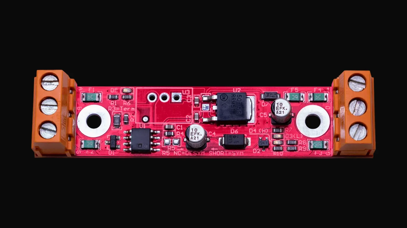
An SPI signal is the weakest link of every large pixel installation. It works perfectly on the bench and then fails once the controller sits in a technical room 40 m away. This article explains how to send an SPI signal over long distance, how long one segment can be, and which device solves which distance.
It is written for integrators, event technicians and lighting designers planning lines of 20 m, 100 m or more. You will leave with a segment calculation, a device comparison and a wiring plan for a 100 m line.
Why Does an SPI Signal Fail Over Long Distance?
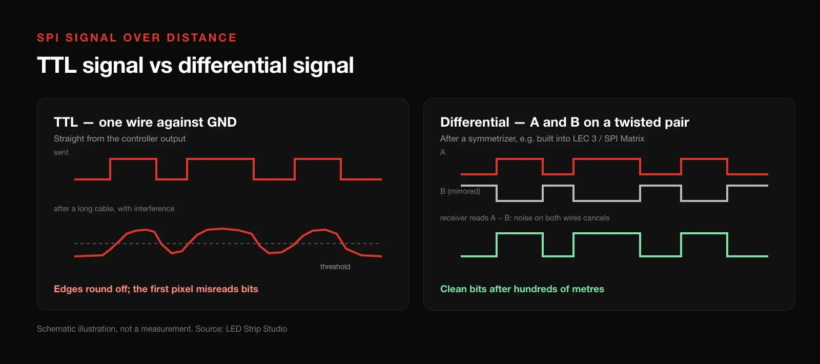
An SPI signal for pixel LEDs is a single-ended TTL data line, measured against GND and switching at around 800 kHz. Every metre of cable adds capacitance and picks up interference. The edges of each bit round off until the first pixel reads a 0 as a 1, and the strip flickers or shows random colours.
That is why we recommend keeping the wire from controller to first pixel shorter than 1 m. Beyond that point the result depends on cable type, driver IC and the electrical noise around the cable. A setup that works in the workshop can fail next to a dimmer rack or a stage motor.
What Is the Difference Between TTL and Differential Signal?
A TTL signal uses one wire and compares it with GND. A differential signal uses two wires, A and B, carrying mirrored copies of the same data. The receiver reads only the difference between them, so noise that hits both wires equally cancels out.
Twisted pair cable is built for exactly this. Converting TTL to a differential signal is what lets data travel hundreds of metres instead of a few. The device that does the conversion is called a symmetrizer, and the conversion back is done right at the strip.
 Source: LED Strip Studio
How Many Pixels and Metres Fit on One SPI Output?
Distance is only half of the problem; the other half is pixel count. One output of an LEC 3 pixel controller or an SPI Matrix drives up to 1,024 RGB or 768 RGBW pixels. At that load the output still holds about 25 frames per second.
The arithmetic explains the ceiling. A pixel on an 800 kHz single-wire IC needs 24 bits, or 30 µs of data. 1,024 pixels therefore take about 31 ms per frame before any overhead, and RGBW reaches the same figure at 768 pixels. Add more pixels and the animation slows down visibly.
The pixel limit turns into a maximum segment length:
| Pixel density | Max segment, RGB (1,024 px) | Max segment, RGBW (768 px) |
|---|---|---|
| 30 px/m | 34.1 m | 25.6 m |
| 60 px/m | 17.0 m | 12.8 m |
| 96 px/m | 10.6 m | 8.0 m |
| 144 px/m | 7.1 m | 5.3 m |
Count pixels, not LEDs. Many 12 V strips drive three LEDs with one IC, so a “60 LED/m” strip may carry only 20 pixels per metre. The datasheet of your strip decides which row applies.
Worked Example: How Do You Wire a 100 m LED Line?
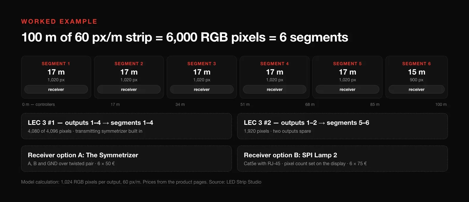
Take a 100 m line of 60 px/m pixel LED strip with the controller at one end. That is 6,000 RGB pixels, so the line splits into six segments: five of 17 m and one of 15 m. The last segment start sits 85 m from the controller, far beyond any TTL cable.
One LEC 3 offers four outputs and 4,096 pixels, so this line needs two controllers. The transmitting symmetrizer is built into both LEC 3 and SPI Matrix. Each segment start therefore needs only a receiver that converts the differential signal back to TTL.
You have two receiver options for each of the six segments:
- The Symmetrizer — wire A, B and GND over twisted pair, 6 × €50.
- SPI Lamp 2 — plug in a Cat5e cable, set the pixel count on the display, 6 × €75.
Pixel density changes the whole design. The same 100 m at 30 px/m is only 3,000 pixels. That fits three segments of about 33 m on a single LEC 3. The same arithmetic applied to a building cornice is worked through in our guide to pixel LED facade lighting.
 Source: LED Strip Studio
Which Device Should Extend Your SPI Signal?
The right device depends on the distance you need to bridge and on the controller you use.
| Device | Typical distance | Signal and cable |
|---|---|---|
| Direct TTL output | under 1 m | TTL, any cable |
| TTL Signal Buffer | 5–10 m | TTL, 2 channels, screw terminals |
| Mini TTL Signal Buffer | 5–10 m | TTL, 2 channels, solder pads |
| The Symmetrizer | up to 500 m | Differential, twisted pair |
| SPI Lamp 2 | up to 100 m per cable run | Differential, Cat5e, RJ-45 |
When Is a TTL Buffer Enough?
A TTL Signal Buffer regenerates the data where one strip ends and a cable begins. It typically carries the signal 5 to 10 m, depending on cable, IC and interference. Its second channel carries the backup line of ICs such as WS2815.
Use it for gaps between strips, not for long feeds. Two buffers in series are possible, but we do not recommend it.
When Do You Need a Symmetrizer?
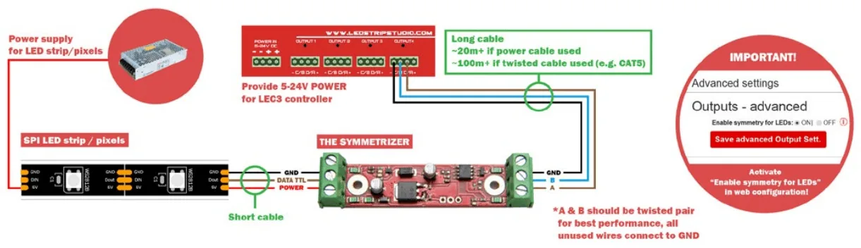
The Symmetrizer converts one data line between TTL and a differential A/B pair, with a GND, B, A port on the differential side. By default it converts differential data to TTL, so it works as the receiver at each segment start. Bridging two solder pads turns it into a transmitter.
With an LEC 3 or SPI Matrix you need it only at the strip end. Switch the controller’s built-in symmetrizer on with Enable symmetry for LEDs under Outputs – advanced in the web configuration.
 Source: LED Strip Studio
With a third-party controller you need a pair: one set as transmitter at the controller and one as receiver at the strip. Step-by-step wiring for both cases is in our long-distance SPI control guide.
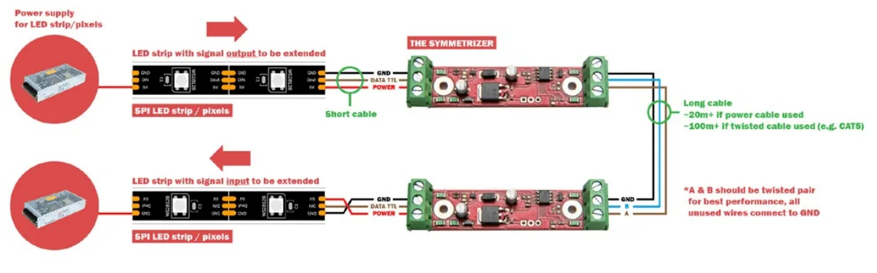 Source: LED Strip Studio
When Is SPI Lamp 2 the Better Choice?
SPI Lamp 2 receives the signal over a standard Cat5e cable. Pixel count and IC type are set on its display, and up to 32 boards daisy-chain on one output. It works only with LEC 3 and SPI Matrix.
Chaining multiplies outputs, not pixels. All lamps on one controller output share its 1,024 RGB pixels. For 17 m segments at full load, plan one lamp per output. Our SPI Lamp guide covers setup in detail.
Which Mistakes Break Long SPI Runs?
Most long-distance faults come from planning, not from broken hardware.
- Running TTL data several metres from the controller. Keep the direct run under 1 m, or add a buffer or symmetrizer.
- Leaving GND out of the data cable. Always route GND next to data, preferably in the same cable.
- Loading an output beyond 1,024 RGB pixels. The frame rate drops below about 25 fps.
- Stacking TTL buffers instead of going differential. Beyond roughly 10 m, switch to a symmetrizer.
- Expecting a lamp chain to add pixels. Every lamp on one output shares the same 1,024-pixel budget.
- Using a Symmetrizer in the wrong mode. The default is receiver; the transmitter mode needs the solder pads bridged.
Planning a long line or a large facade? Book a free consultation with our team.
Summary
A pixel LED SPI signal is a single-ended TTL line, so it is reliable only for about a metre between controller and first pixel. For longer runs it has to become a differential A/B signal on twisted pair: The Symmetrizer carries it up to 500 m, SPI Lamp 2 up to 100 m per Cat5e hop, and LEC 3 and SPI Matrix already contain the transmitting symmetrizer, so only receivers are needed at the strips. Distance is half the design; the other half is the 1,024 RGB or 768 RGBW pixels one output can drive at about 25 fps, which limits a 60 px/m segment to about 17 m. A 100 m line at that density needs six segments and two controllers.