Technology
What Is SK6812? RGB vs RGBW, Specs and How to Control It
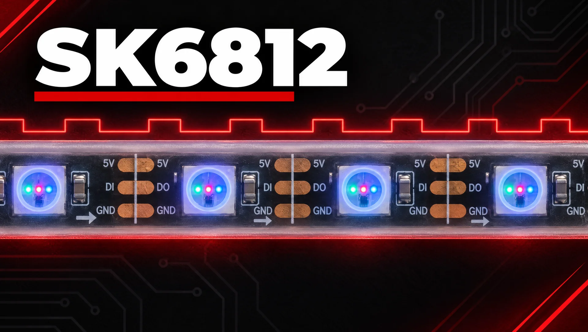
SK6812 is an addressable LED driver IC used in pixel strips, modules and matrices. It speaks almost the same single-wire protocol as WS2812B, and it is the chip most strips use when they need a dedicated white channel. That white channel changes how many pixels one controller output can drive and how you configure it.
This guide explains what the chip is, how its protocol works and how the RGB and RGBW versions differ. It also shows how many pixels one controller output can drive and how to plan, wire and control an installation. It is written for integrators, event technicians and lighting designers who specify or troubleshoot these strips on real projects.
What Is SK6812 and Where Is It Used?
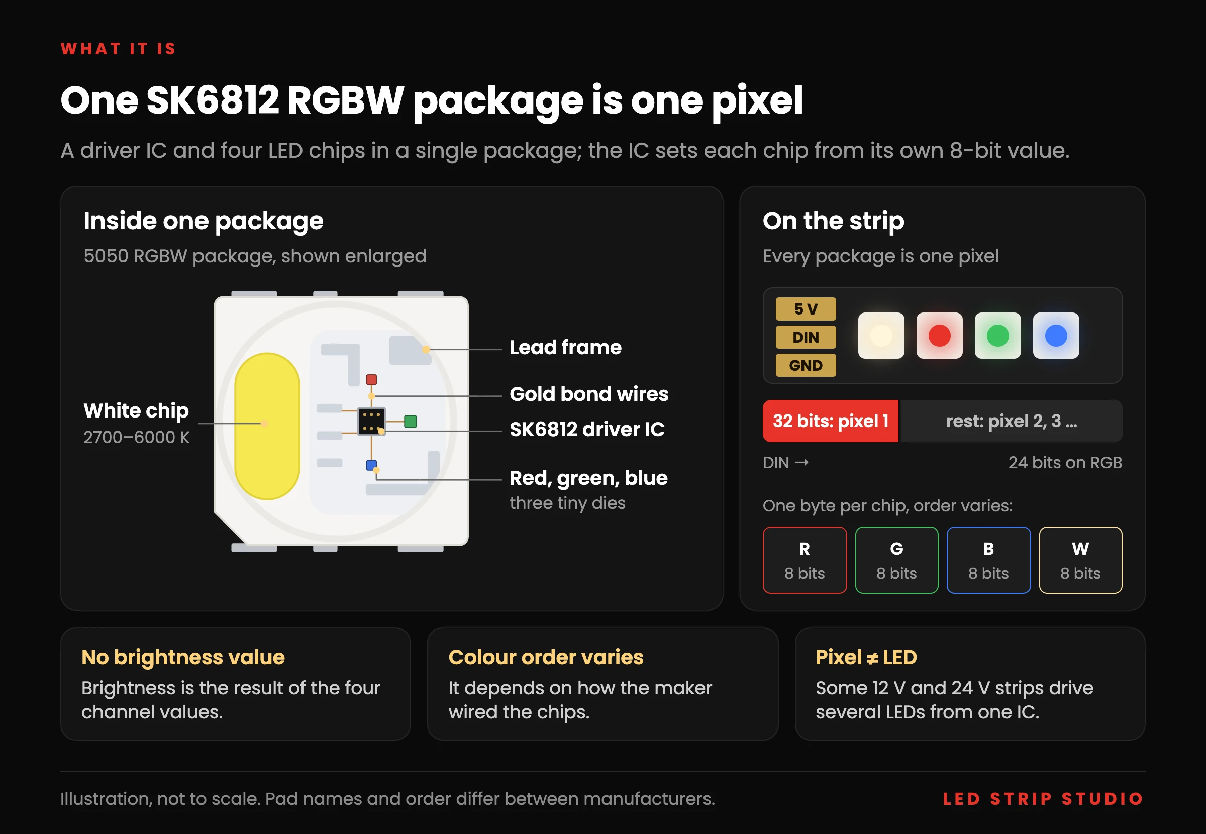
SK6812 is an addressable LED driver: a small integrated circuit (IC) that switches the LED chips connected to its outputs. In most strips it sits inside the same 5050 or 3535 package as the LED chips, so one package is one pixel. One package can hold several LED chips, typically one red, one green and one blue, and in RGBW versions a white one as well.
Each output of the IC receives its own 8-bit value, so the controller sets every colour channel of every pixel separately. The chip receives no separate brightness value; brightness is simply the result of the channel values.
You find the chip in flexible strips, rigid bars, modules and matrices for architectural, retail and event lighting.
Which SK6812 Variants Exist?
The IC itself is one component. Manufacturers connect different LED chips to its outputs and mount it in different packages, so strips sold under this name differ in three independent ways:
- Outputs and colours — the three-output version drives RGB, or any other three LED chips such as warm white, white and amber (WWA). WWA is not the same as CCT, which mixes only warm and cool white. The four-output version adds a white chip in warm, natural or cool white (RGBW).
- Package size — the standard 5050 package, the smaller 3535 for narrow strips, and the side-emitting 4020 for edge lighting.
- Supply voltage and LEDs per pixel — most strips run at 5 V, but 12 V and 24 V versions exist too. A 12 V pixel can still be a single LED, while other 12 V and 24 V strips drive several LEDs from one IC, all showing the same colour.
Because any LED chip can be wired to any output, the order in which a strip expects colour data is not fixed. This colour order depends on how the manufacturer connected the chips, and it is the most common configuration fault we see.
How Does the SK6812 Protocol Work?
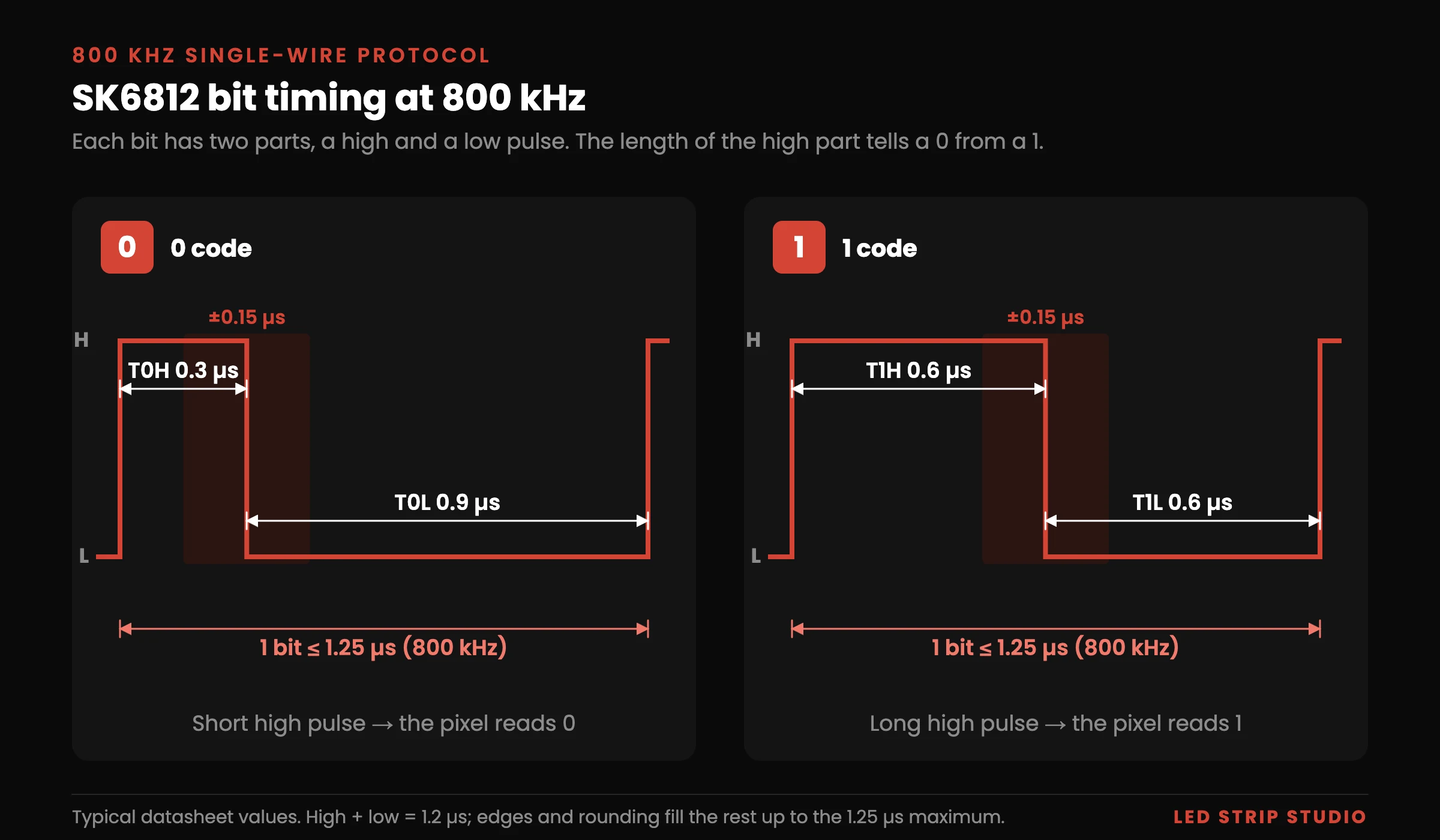
The chip uses a single-wire, self-clocked protocol at 800 kHz. There is no separate clock line, unlike APA102-style strips, so the pixel decodes each bit from pulse timing alone.
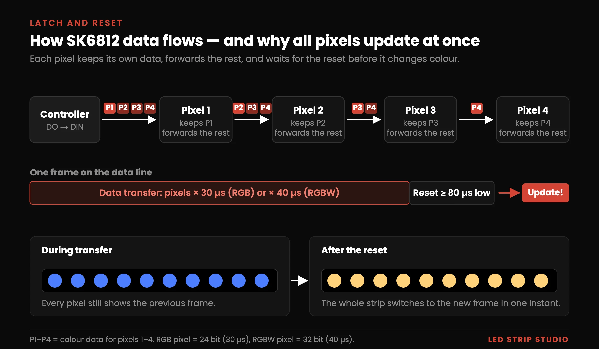
Data flows in one direction only. The controller sends a full frame into the first pixel. The pixel keeps the first 24 bits of the stream (32 on RGBW) for itself and forwards all following bits, reshaped, to the next pixel. Every pixel along the strip repeats this until the frame runs out.
How Are Bits Encoded at 800 kHz?
Every bit consists of two parts: a high pulse followed by a low pulse. The length of the high part decides whether the pixel reads a 0 or a 1. According to the datasheet, a 0 is about 0.3 µs high and 0.9 µs low, and a 1 is about 0.6 µs high and 0.6 µs low.
The two parts add up to 1.2 µs, while one bit may last up to 1.25 µs. That gap is not an error: rising and falling edges also take time, and the datasheet values are rounded. Each pulse has a tolerance of roughly ±0.15 µs, and a controller that misses it produces random flicker and wrong colours. That is why pixel controllers generate these pulses in hardware rather than in software loops.
What Does 8 Bits per Colour Mean?
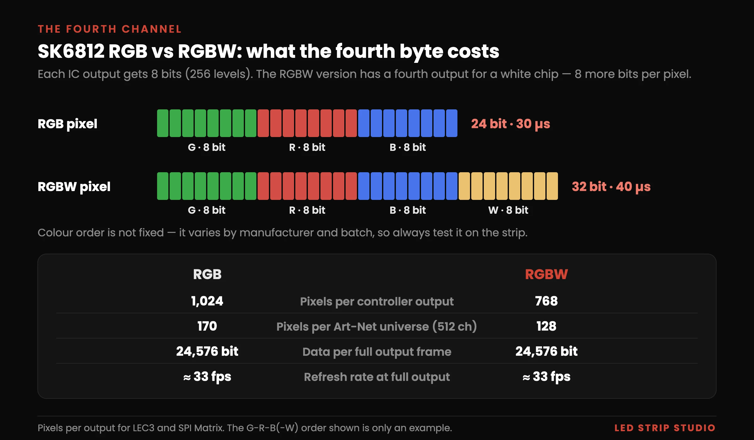
Each output channel receives 8 bits, which gives 256 levels from 0 to 255. An RGB pixel therefore needs 24 bits and an RGBW pixel 32 bits. At 1.25 µs per bit, one RGB pixel occupies 30 µs on the wire and one RGBW pixel 40 µs.
LED brightness does not follow these values linearly. At the very bottom and top of the range, two neighbouring values can look almost the same, or even identical. Some LEDs only start to glow visibly from a value of around 10, so test very dim scenes and slow fades to black on the real strip.
Why Do All Pixels Update at Once?
The pixels do not change colour while data passes through them. Each pixel stores its new value in an internal latch and keeps showing the previous frame. Only when the data line stays low for the reset time do all pixels switch to their new values together.
The classic datasheet asks for a reset of at least 80 µs, and some newer revisions ask for more than 200 µs. Thanks to the latch, the whole strip repaints in one instant, with no visible wave running along it. The frame rate does not depend on this mechanism; as with every single-wire pixel IC, it depends on how many pixels the data has to pass.
SK6812 RGB vs RGBW: What Is the Difference?
The RGBW version of the IC has one more output, so a fourth LED chip, usually white, can be connected to it. Each pixel then needs a fourth byte of data. The white chip comes in warm, natural or cool white.
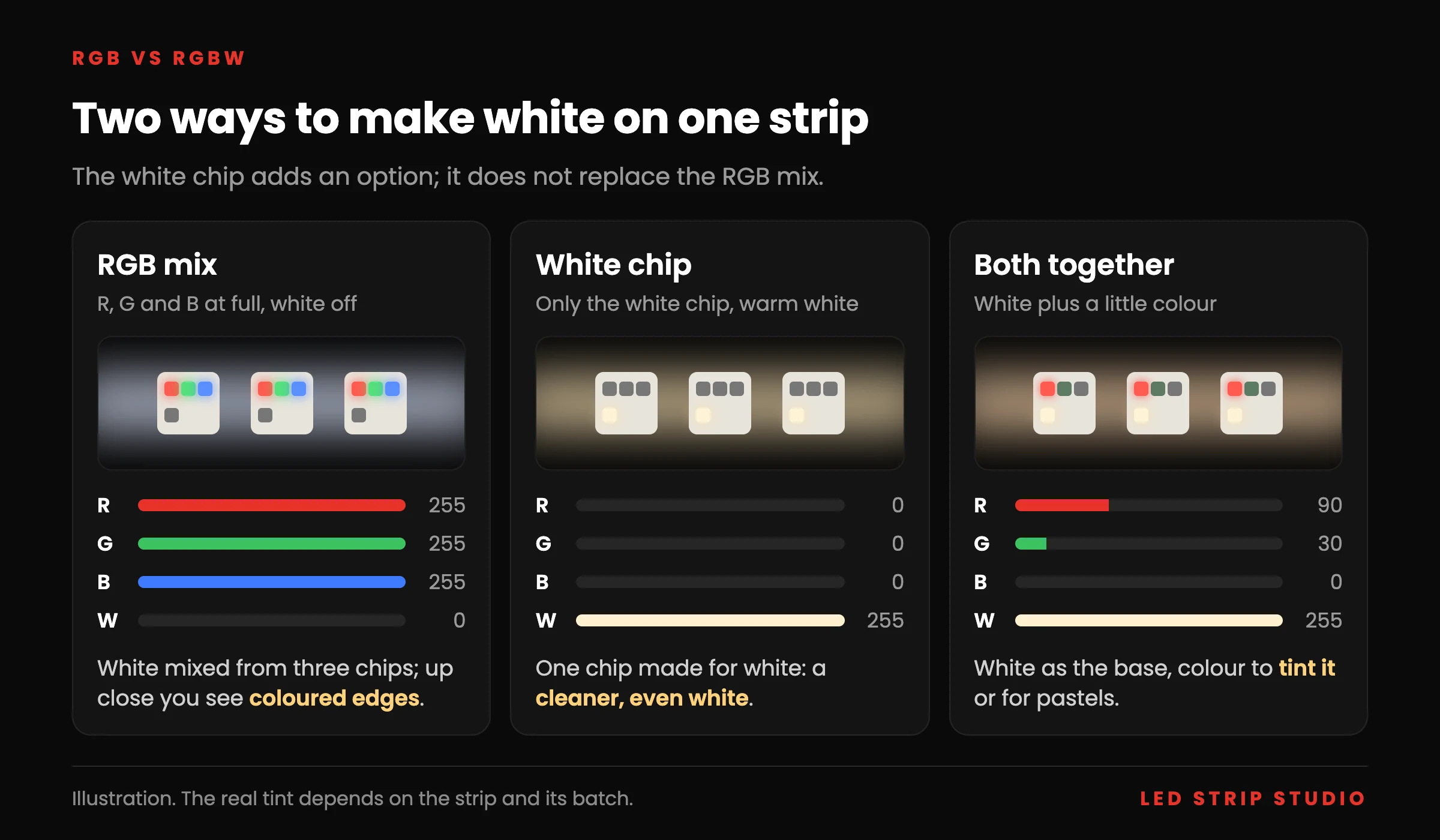
White mixed from red, green and blue is still available on an RGBW strip. The white chip adds an option rather than replacing the mix. Whether a scene uses RGB, W or both is decided in the controller, the animation or the template, never by the chip. A dedicated white chip simply makes clean whites and pastel tones easier to reach.
The fourth byte has a price elsewhere in the system: it cuts pixels per output and per Art-Net universe by a quarter. The table collects the key specs of both versions. Exact figures differ between manufacturers and datasheet revisions, so always check the datasheet of the strip you buy.
| Parameter | RGB version | RGBW version |
|---|---|---|
| Outputs (channels) per pixel | 3 | 4 |
| Bits per pixel (8 per channel) | 24 | 32 |
| Time on the wire per pixel | 30 µs | 40 µs |
| Colour order | Varies by maker and batch | Varies by maker and batch |
| Protocol and data rate | Single wire, 800 kHz | Single wire, 800 kHz |
| Reset (latch) time | ≥ 80 µs; some revisions > 200 µs | ≥ 80 µs; some revisions > 200 µs |
| Typical supply | 5 V; 12 V and 24 V versions exist | 5 V; 12 V and 24 V versions exist |
| PWM frequency | 1 kHz (SK6812-012) | Depends on revision |
| Backup data line | None | None |
| Pixels per output (LEC3, SPI Matrix) | 1,024 | 768 |
| Pixels per Art-Net universe | 170 | 128 |
| White light | Mixed from R, G and B | Mixed from R, G and B, from the white chip, or both |
| Best suited for | No need for a white chip, most pixels per output | Clean white plus colour in one strip |
When Is the White Channel Worth It?
Choose RGBW when the installation spends much of its life in white or near-white. Bars, hotels, retail and facades often run white during opening hours and colour only for events. The white chip gives a cleaner white than the RGB mix, and you can still combine it with colour.
Choose RGB when you do not need the white chip or when you need as many pixels per output as possible: 1,024 instead of 768. Colour saturation is the same on both, because the red, green and blue chips are usually identical. If you go RGBW, fix the white temperature before ordering, because warm, natural and cool batches look different side by side.
What Happens When an SK6812 Pixel Fails?
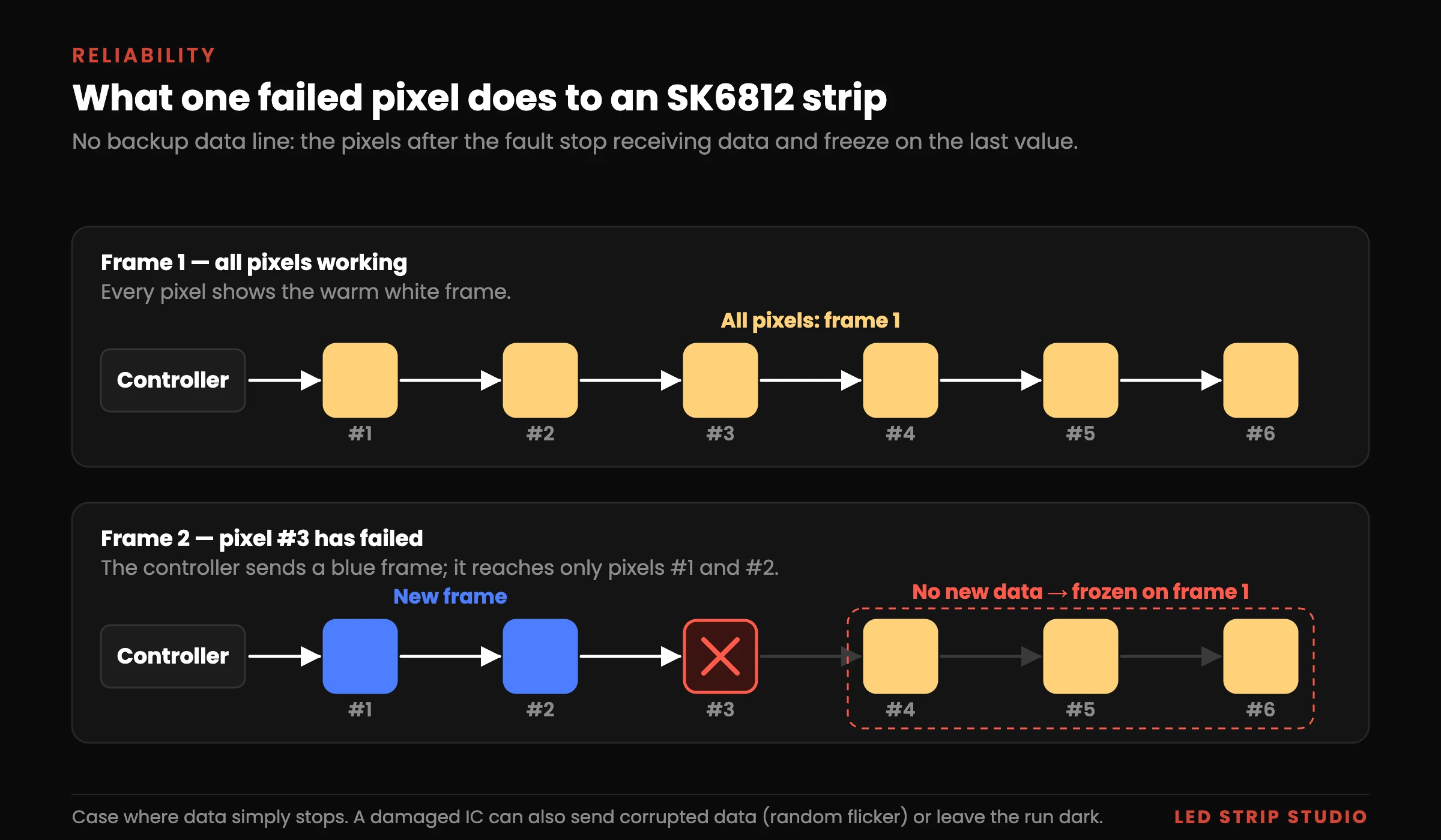
It depends on how it fails. If the data simply stops, the pixels after the fault keep the last value they received, so the rest of the run freezes on the last frame. A damaged IC can also pass on corrupted data, which makes the rest of the run flicker randomly, and a fault in the power path can leave it dark.
The IC has one data input and one data output, so there is no second path around a failed pixel and no backup wire to connect. Plan access to the strip and buy spare segments together with the installation. A reel ordered later often comes from another batch with slightly different colours, which shows next to the original strip, and cameras make it even more visible. ICs such as WS2815 and WS2814 add a backup data line, but it helps only in the cleanest case, when the failed pixel stops sending data altogether. Our guide explains how the WS2815 backup data line works and where it falls short.
How Does SK6812 Compare to WS2812B and WS2815?
| Parameter | SK6812 | WS2812B | WS2815 |
|---|---|---|---|
| Strips on the market | RGB, RGBW, white, WWA | RGB, white, CCT, WWA | RGB, RGBW, white, WWA |
| Bits per pixel | 24 / 32 | 24 | 24 / 32 |
| Supply | 5 V, 12 V, 24 V | 5 V | 12 V, 24 V |
| LEDs per pixel | 1 or more | 1 | 1 |
| PWM frequency | 1 kHz (SK6812-012) | 400 Hz older / 2 kHz newer | 2 kHz |
| Backup data line | No | No | Yes |
The colour configuration says little about the IC itself, because any of these chips can drive whatever LED chips the manufacturer connects. What really separates them is the supply voltage, the PWM frequency and the backup data line. The RGB version and WS2812B use the same interface, so their strips can often be chained. Check the colour order of each strip first, because it may differ even between two reels.
How Many SK6812 Pixels Can One Output Drive?
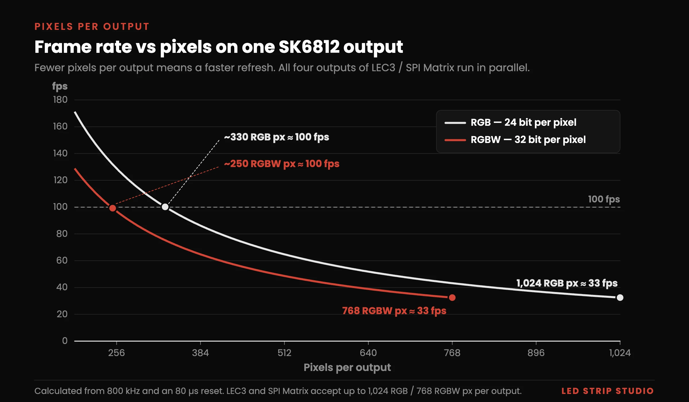
One output of an LEC3 pixel controller for SK6812 or an SPI Matrix drives up to 1,024 RGB or 768 RGBW pixels at about 33 frames per second. All four outputs run in parallel, so a PRO-tier unit drives 4,096 RGB or 3,072 RGBW pixels at that rate. The two pixel figures per output are equal by design: 1,024 × 24 bits and 768 × 32 bits are both 24,576 bits.
The arithmetic is short. 24,576 bits × 1.25 µs gives 30.7 ms per frame, plus the reset pause, which is about 33 fps.
Fewer pixels per output means a faster refresh. With about 330 RGB or 250 RGBW pixels on an output, the line refreshes at around 100 fps, which helps on camera and with fast effects. Treat 1,024 and 768 as the maximum one output accepts, not as a target to fill.
How Long Can One Run Be per Output?
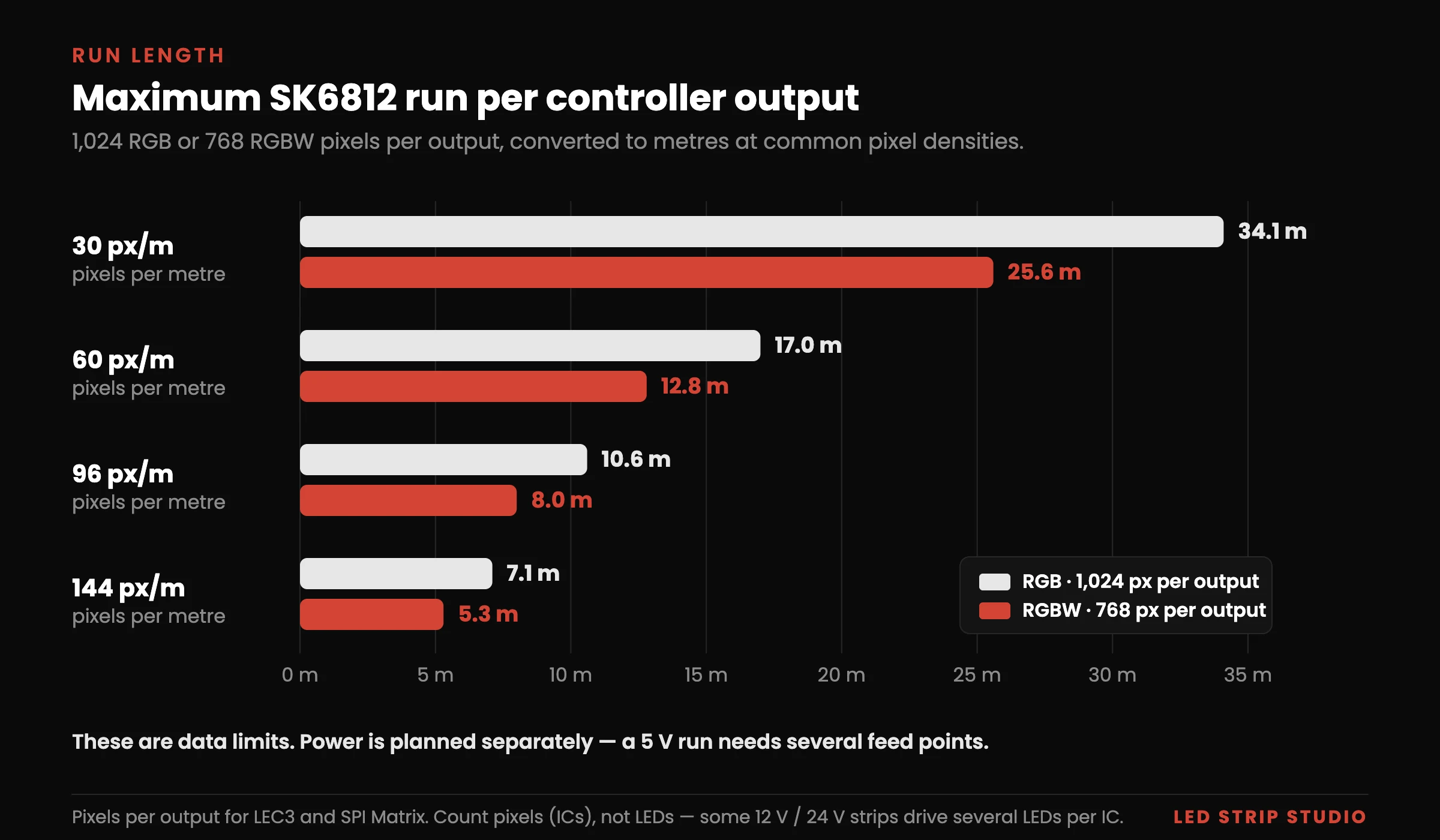
The pixel limit turns directly into a maximum run length per output.
| Pixel density | Max run, RGB (1,024 px) | Max run, RGBW (768 px) |
|---|---|---|
| 30 px/m | 34.1 m | 25.6 m |
| 60 px/m | 17.0 m | 12.8 m |
| 96 px/m | 10.6 m | 8.0 m |
| 144 px/m | 7.1 m | 5.3 m |
These are data limits. Power is planned separately, as described in the power section below.
How Many Art-Net Universes Do RGB and RGBW Need?
One universe carries 512 channels, which holds 170 RGB pixels or 128 RGBW pixels. A full RGBW output of 768 pixels fills exactly 6 universes. A full RGB output of 1,024 pixels needs 7, or 6 if you plan it at 1,020 pixels.
In the default setting each output starts on a new universe, so you round per output. That is a setting, not a rule: with few pixels you can patch several outputs, even all four, into one universe. Our Art-Net universe calculator handles both cases.
Example: How Would You Plan an RGBW Bar Counter?
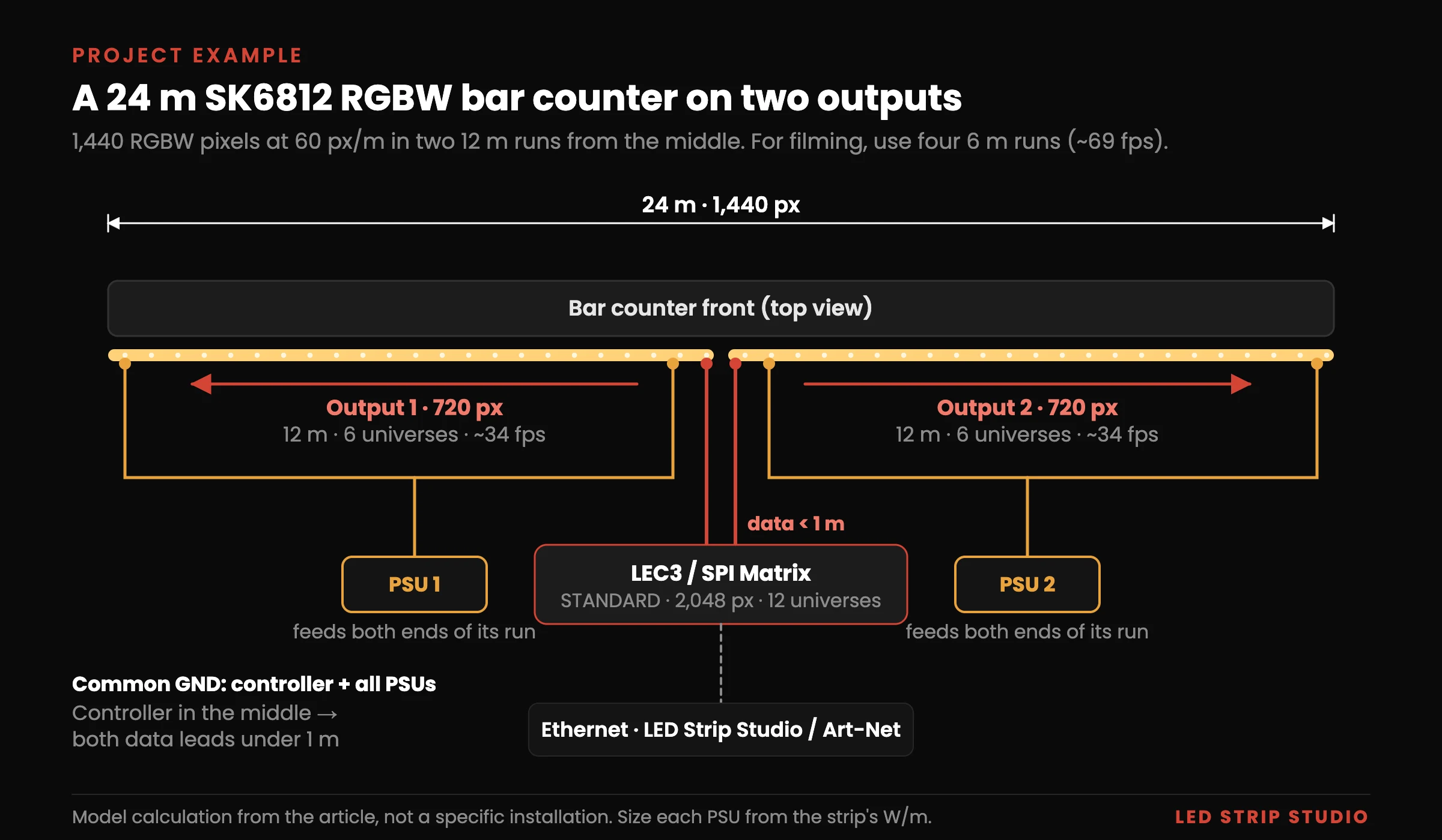
Take a typical hospitality brief: a 24 m bar counter edge, warm white during opening hours and colour scenes for events. White comes first in this brief, which makes it a clear case for an RGBW strip with a warm white chip. At 60 px/m the counter carries 1,440 pixels.
One output takes 768 RGBW pixels, which is 12.8 m at this density. The counter can therefore split into two runs of 12 m with 720 pixels each, refreshing at about 34 fps. If the bar is filmed, split it into four runs of 6 m instead. With 360 pixels per output the refresh rate doubles to about 69 fps, which looks smoother on camera.
| Item | Layout A: 2 outputs | Layout B: 4 outputs |
|---|---|---|
| Strip | SK6812 RGBW, warm white, 60 px/m | SK6812 RGBW, warm white, 60 px/m |
| Total length and pixels | 24 m, 1,440 px | 24 m, 1,440 px |
| Runs | 2 × 12 m, 720 px each | 4 × 6 m, 360 px each |
| Refresh rate per output | ~34 fps | ~69 fps |
| Art-Net universes (default patch) | 12 (6 per output) | 12 (3 per output) |
| Controller | 1 × LEC3 STANDARD (2,048 px) | 1 × LEC3 STANDARD (2,048 px) |
| Signal to first pixel | Under 1 m, or symmetrizer + desymmetrizer | Under 1 m, or symmetrizer + desymmetrizer |
Both layouts fit one LEC3 STANDARD, which drives 2,048 RGB or 1,536 RGBW pixels with 12 universes. You do not need the 4,096-pixel PRO tier; the differences between LITE, STANDARD and PRO are explained separately. Content is then built once in LED Strip Studio 4, and filmed venues are covered in our article on pixel LED for TV studios.
How Do You Control SK6812 Step by Step?
A DIY setup with a microcontroller and open-source firmware can drive these strips, and it is a good way to learn. For commercial installations it rarely pays off: timing, mapping, networking and long-term reliability take a lot of time to get right. A ready-made pixel controller is usually simpler and, once your time is counted, cheaper.
Which Pixel Controller Suits an Installation?
Whatever controller you choose, it has to support the exact IC: SK6812 RGB or RGBW, with a selectable colour order that includes the white channel. On LEC3 and SPI Matrix you set the chip type for each output in the web configuration. The full list of chips is on our supported LED IC page.
LEC3 and SPI Matrix both have four outputs, accept Art-Net from a console or media server and can run standalone without a computer. LEC3 can also be controlled live from LED Strip Studio software. The product pages of LEC3, SPI Matrix and Reactivo 2 list all control options.
How Far Can the Data Signal Travel?
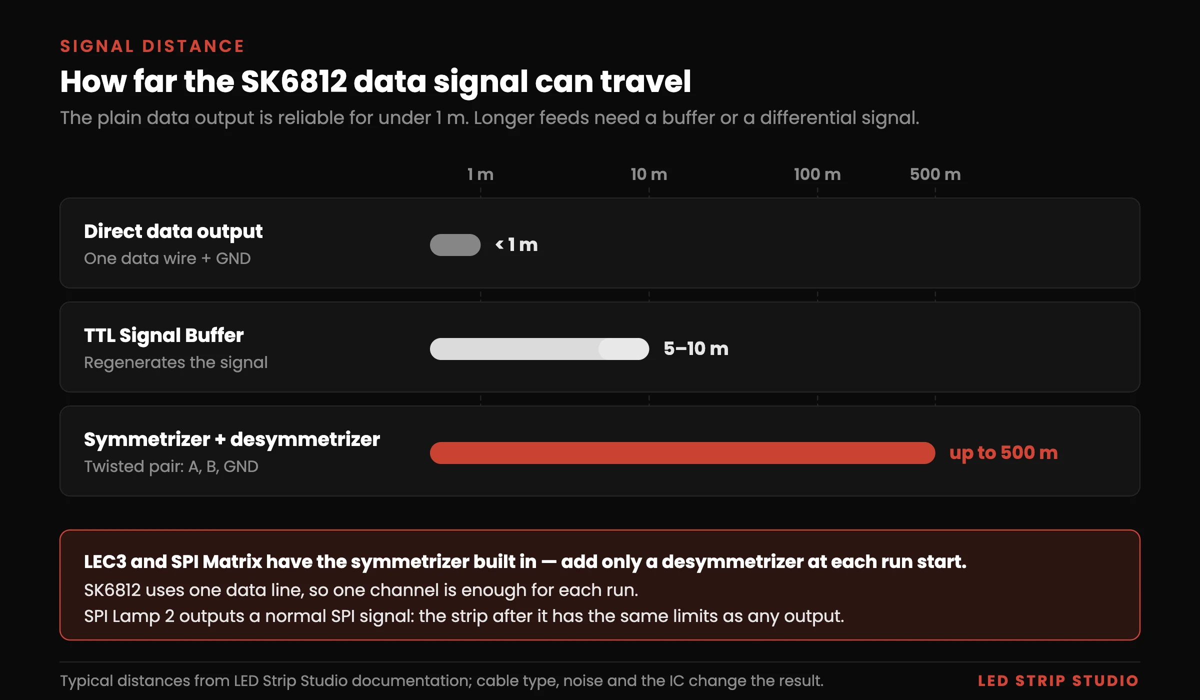
The datasheet allows more than 10 m between two pixels, but that depends on cable quality, signal level and electromagnetic interference. The controller output is a plain signal on one data wire measured against GND, and we recommend a data cable of up to 1 m to the first pixel. On longer cables, capacitance and interference deform the short pulses, pixels misread bits and the strip shows wrong colours.
For longer feeds, convert the data to a differential signal over twisted pair. That takes two parts: a symmetrizer at the controller and a desymmetrizer at the start of the run. LEC3 and SPI Matrix have the symmetrizer built in, so you add only a desymmetrizer at each run start, up to 500 m away. The protocol needs only one data line, so one channel is enough.
SPI Lamp 2 receives its own signal over Cat5e, which is also differential, and outputs a normal SPI signal, so the strip after it has the same pixel limits as any controller output. A TTL Signal Buffer bridges 5–10 m gaps between strips. Our guide to sending an SPI signal over long distance has the full calculation.
How Do You Power 5 V Pixel Strips?
Power is planned separately from data, and the principles are the same for every pixel strip. Size each supply from the strip’s W/m at full brightness, feed every run at more than one point, and connect all GNDs together. Our WS2815 guide walks through power injection and supply sizing in detail. At 5 V the same power means 2.4 times the current of a 12 V strip, so plan more feed points.
Mount the strip in an aluminium profile, which protects it and carries heat away; good heat dissipation extends the life of the strip.
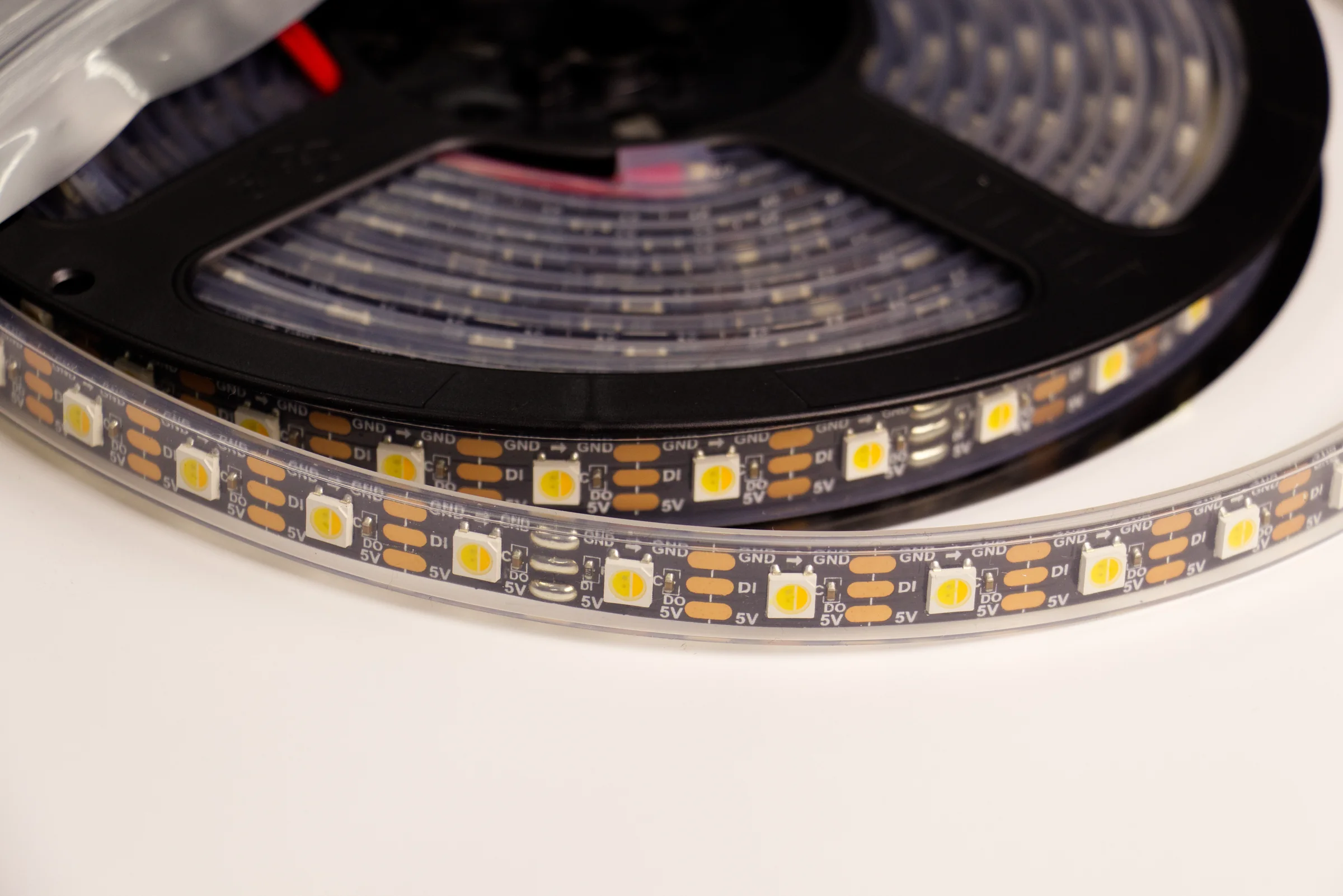
An SK6812 5 V pixel strip from our shop.
What Are the Setup Steps?
- Identify the exact strip: RGB or RGBW, white temperature, supply voltage and LEDs per pixel.
- Split the installation into runs of up to 1,024 RGB or 768 RGBW pixels per output, or fewer for a higher frame rate.
- Place the controller within 1 m of each run start, or add a symmetrizer and desymmetrizer.
- Plan the power distribution: supply sizes, feed points along every run, cable cross-sections and a common GND.
- Set the chip type and colour order for each output, then test solid red, green, blue and white.
- Create the pixel mapping and check the pixel count of every output, for example by lighting only the last pixel.
- Choose how the installation will be controlled: live from software or a console, or standalone.
- Set up that control method and test it end to end, including a power cycle.
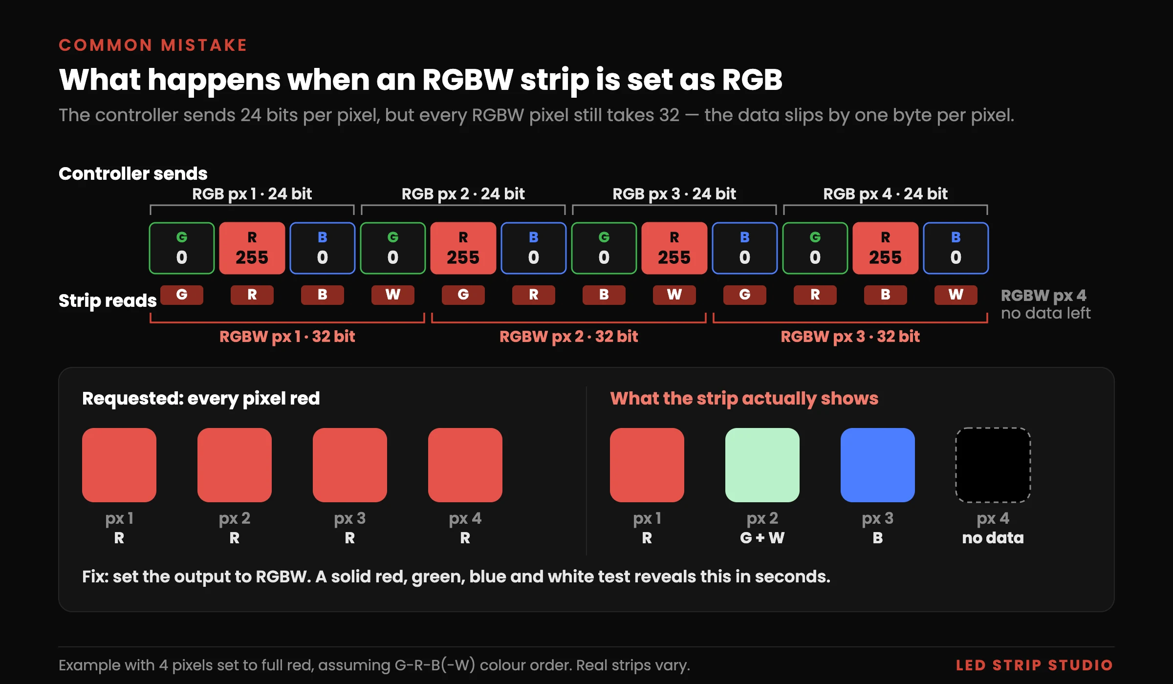
The solid-colour test in step 5 catches a wrong colour order in seconds, including a white channel in the wrong position.
Which SK6812 Mistakes Cost the Most?
Most faults we are asked about come from configuration and planning, not from broken LEDs.
- Configuring an RGBW strip as RGB, or the other way round. The bits per pixel no longer match, so colours scramble along the run; an RGBW strip set as RGB also leaves its last quarter without data.
- Assuming the colour order. It varies between manufacturers, between batches and sometimes within one reel, so test every reel.
- Expecting a dead pixel to be bypassed. There is no backup line, so the pixels after a failure usually freeze on their last value or flicker.
- Running the plain data wire several metres from the controller. Keep it under 1 m or switch to a differential signal.
- Counting LEDs instead of pixels. On some 12 V and 24 V versions one IC drives several LEDs, which changes every limit above.
- Filling every output to the limit in a filmed space. Fewer pixels per output give a higher frame rate, so a four-output layout often looks better on camera.
Planning an RGB or RGBW pixel installation and unsure about outputs, power or signal distance? Book a free consultation with our team.
Frequently Asked Questions
Is SK6812 the same as WS2812B?
Not exactly. The RGB version uses the same 800 kHz single-wire interface, so it often works as a drop-in replacement. Unlike WS2812B, it also exists as a four-output RGBW version.
Does SK6812 run at 5 V, 12 V or 24 V?
Most strips run at 5 V, but 12 V and 24 V versions exist. A 12 V pixel can be a single LED, while other versions drive several LEDs from one IC, so check how many LEDs form one pixel. Do not rely on the LEDs-per-metre figure, which some makers quote as LEDs and others as pixels.
What colour order does an SK6812 strip use?
There is no fixed order. It depends on how the LED chips were connected to the IC, and it can differ between suppliers, between batches of the same product and even within one reel. Always confirm it with a solid red, green, blue and white test.
How many pixels fit on one controller output?
On LEC3 and SPI Matrix, up to 1,024 RGB or 768 RGBW pixels per output at about 33 fps, on all four outputs at once. Fewer pixels per output give a higher frame rate, up to around 100 fps.
What happens when one pixel on the strip fails?
If the data simply stops, the pixels after it freeze on the last value they received. A damaged IC can also cause random flicker, or a dark section if the power path is hit. A backup data line, as on WS2815, helps only when the failed pixel stops sending data.
Can SK6812 be controlled directly over DMX or Art-Net?
No. The strip only understands its own single-wire signal, so you need a controller that converts DMX or Art-Net into it. Some fixtures and LED ICs accept DMX directly, but SK6812 is not one of them; our guide to controlling LED strips over DMX covers the basics.
Summary
SK6812 is an addressable LED driver IC with a single-wire 800 kHz protocol and 8 bits per output channel: 24 bits per RGB pixel and 32 per RGBW pixel. The RGBW version has a fourth output for a white chip; RGB mixing stays available and saturation does not change. All pixels latch their data and repaint together after the reset, and the frame rate depends on the number of pixels. There is no backup data line: after a failed pixel the rest of the run usually freezes on its last value, and a damaged IC can also cause flicker. One LEC3 or SPI Matrix drives 4 × 1,024 RGB or 4 × 768 RGBW pixels at about 33 fps, and fewer pixels per output give up to around 100 fps.
Sources & references
- Dongguan Opsco Optoelectronics — SK6812 Technical Data Sheet: 800 kHz, T0H 0.3 µs / T1H 0.6 µs, bit period up to 1.25 µs, reset 80 µs, ≥ 1,024 pixels at 30 fps
- Opsco — SK6812RGBW Specification: 32-bit data
- Opsco — SK6812-012 datasheet, newer revision: reset > 200 µs
- ENTTEC — SK6812 Pixel Protocol: 24/32-bit, no redundant data line
- LED Strip Studio — internal comparison of supported LED ICs: PWM frequency, behaviour on data loss, pixels per output
- LED Strip Studio — LEC3 and SPI Matrix product pages: 1,024 RGB / 768 RGBW pixels per output, LITE / STANDARD / PRO tiers
- LED Strip Studio — Supported LED chips
- LED Strip Studio — What Is WS2815?, How Do You Send an SPI Signal Over Long Distance? and Art-Net Universe Calculator