Technology
What Is an SPI Lamp and When Should You Use One?
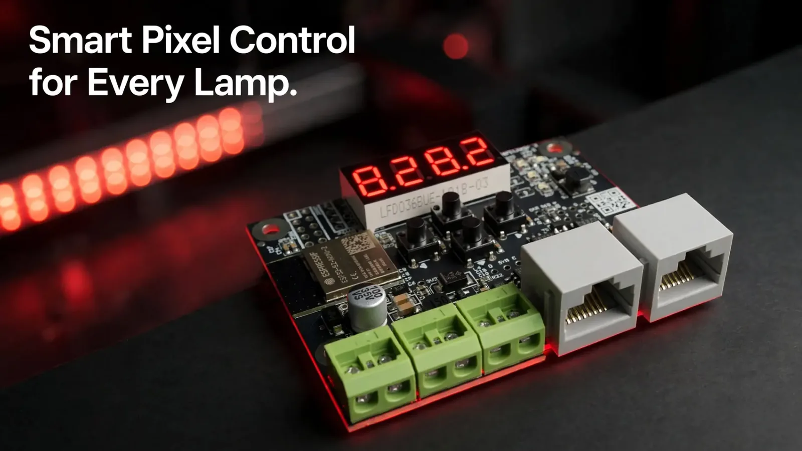
Most addressable pixel installations lose time and money on one repetitive task: dragging a data cable from the end of one strip to the start of the next. SPI Lamp 2 removes that step. It’s a small signal splitter that takes SPI data from a controller output over standard RJ-45/Cat5e cable, then gives you an independent output right where you need it.
This article explains what SPI Lamp 2 does, where its real limits sit, how to set one up, and where it pays for itself. It’s written for integrators, event technicians, lighting designers, and advanced DIY builders.
What Is SPI Lamp 2 and How Does It Work?
SPI Lamp 2 is a compact board that solves SPI signal distribution. Instead of routing one long SPI run from object to object—which causes signal integrity issues even over a few metres—it turns a single controller output into as many independent physical outputs as your project needs.
The first job installers notice immediately: strips no longer have to be chained end to end, because each segment gets its own SPI Lamp 2. Data arrives over RJ-45/Cat5e straight from the controller output, not through the previous strip. That removes wire runs, connectors, and labour from the job.
The second job is output multiplication. An LEC3 or SPI Matrix gives you four physical outputs, which is enough for many projects but not all. SPI Lamp 2 daisy-chains up to 32 units from a single output, or branches into two independent runs with Y-Splitting. You place small units where you need them instead of finding space for a second controller.
Why Does SPI Lamp 2 Use RJ-45/Cat5e Cable?
The controller sends data over a custom, interference-resistant protocol called LSS strip 2, running at 2.5Mbps, and standard RJ-45/Cat5e cable carries that signal reliably over distance—up to 100m per hop. It’s also cheap, standardised, and available in almost any computer shop.
That cable is not a regular Ethernet connection. Never plug SPI Lamp 2 directly into a PC network card, switch, or router—its RJ-45 ports use a different pinout, voltage, and protocol from standard 10/100/1000 Mbps Ethernet.
Both RJ-45 ports on the board work as input or output and are auto-detected. If the incoming signal is fed into Port 2 instead of Port 1, the unit takes the pixels it needs from the end of the incoming data rather than the start, and forwards the rest out the other port—this is what makes both daisy-chaining and Y-Splitting possible from the same two ports.
What Can One SPI Lamp 2 Actually Handle?
Plan your segment lengths around the numbers below.
| Parameter | Value |
|---|---|
| Max controllable pixels | 1024 RGB or 768 RGBW per output (0 is a valid minimum) |
| Signal protocol | Custom LSS strip 2, 2.5Mbps |
| Cable | Standard RJ-45/Cat5e |
| Specified cable length | 100m per hop |
| Daisy-chain length | Up to 32 units from one output |
| Compatible controllers | LEC3, SPI Matrix (or later) |
| Not compatible with | Reactivo, SPI LED Controller, or the original SPI Lamp |
| Connectors | 2× RJ-45, both ports auto-detect input or output |
| Board size | 70 × 58 × 18mm, 4 mounting holes |
| DMX output | Yes—select IC type 16 or 17 on the device |
Controller compatibility is a hard limit, not a recommendation. SPI Lamp 2 only works behind an LEC3 or SPI Matrix, because it runs on our own LSS strip 2 protocol—no other controller speaks it. It’s also not backward-compatible with the original SPI Lamp, which used a different protocol version; don’t mix the two in the same chain.
How Do You Set Up SPI Lamp 2 Step by Step?
The sequence below assumes an LEC3 and strips already cut to length.
- Run RJ-45/Cat5e cable from a controller output to the first SPI Lamp 2 unit.
- Daisy-chain the following units from the second RJ-45 port on each board, or use Y-Splitting to branch into two runs.
- Power each SPI Lamp 2 unit—it ships as a bare PCB with no power supply included, so plan a supply for the board itself as well as for the strip it drives.
- On the device, use the 4 built-in buttons (Up/Down/Back/Enter) and display to set the IC type and pixel count for that output.
- In LED Strip Studio 4, build your pixel map so effects travel across the whole structure, not just along one cable.
- Check the output on every unit before closing up enclosures.
Configuration lives entirely on the device—no PC, no software-side strip-type toggle, no SD card required for basic setup. For bulk configuration across many units, you can also set IC type and pixel count via an SpiLamp2.cfg file on an SD card in your LEC3 or SPI Matrix.
What Does the On-Device Display Show?
Beyond IC type and pixel count, the display doubles as a diagnostic tool: voltage, FPS, and firmware version are all available directly on the unit, without connecting a PC.
Project Example: How Does SPI Lamp 2 Wire 12 Lines in a Club?
A club client had one LEC3 and twelve strips of roughly 10m, with 5m between neighbouring lines. Conventionally, data has to leave the end of one strip and travel 5m to the start of the next. At that distance the run usually needs a buffer or a repeater, plus the labour to install both.
With SPI Lamp 2, the strips never connect to each other. Twelve strips were split across four outputs, three units per output—well inside the 32-unit daisy-chain limit per output. The controller stayed in the technical room, with standard Cat5e cable running out to each line.
| Criterion | Strip-to-strip wiring | One SPI Lamp 2 per segment |
|---|---|---|
| Data path between segments | Along the strip, end to start | RJ-45/Cat5e from the controller |
| Cable between lines 5m apart | Custom data cable + buffer/repeater | Standard Cat5e patch cable |
| Controller to first pixel | Limited by SPI over plain cable | Up to 100m per hop |
| Outputs per controller | 4 | Up to 32 per output, or Y-Split |
| Extra hardware per segment | Buffer, repeater, connectors | One SPI Lamp 2 |
Comparable builds—including a large LED tree where every hanging strip on a circular truss ran its own signal splitter, configured on site—are collected in our project portfolio.
Which SPI Lamp 2 Mistakes Cost the Most on Site?
Most faults we’re asked about are configuration or cabling mistakes, not broken boards.
- Plugging SPI Lamp 2 into a network switch or PC. Its RJ-45 ports look like Ethernet but use a different pinout, voltage, and protocol—never connect it to standard network gear.
- Mixing SPI Lamp and SPI Lamp 2 in one chain. The two use different protocol versions and aren’t compatible with each other.
- Guessing the IC type instead of checking it on the device. The display and buttons make this a two-minute check before you close the enclosure.
- Forgetting the board needs its own power. SPI Lamp 2 ships as a bare PCB with no supply included.
- Bridging the positive rail between segments on different supplies. Two separate power sources should never share a + connection.
Planning an installation with segments far apart? Book a free consultation with our team.
Summary
SPI Lamp 2 is a compact signal splitter that sits between an LEC3 or SPI Matrix output and your strips, so segments never have to be wired end to end. One controller output daisy-chains up to 32 units—or branches into two independent runs with Y-Splitting—each driving up to 1024 RGB or 768 RGBW pixels over standard RJ-45/Cat5e cable, up to 100m per hop. IC type and pixel count are set directly on the device via its display and four buttons, no PC or software-side toggle required, and the same 4-pole output can generate real DMX512 instead of SPI when you need it. It pays off wherever segments sit far apart—from a twelve-line club install to a large touring rig.