Technology
How Do You Wire LED Strips to PSL2 Without Voltage Drop?
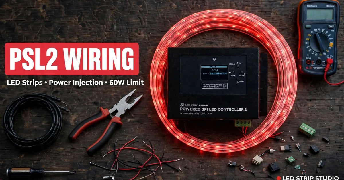
White at the start, yellow at the end. Your controller isn’t broken. The end of the strip just isn’t getting enough power. This guide covers PSL2 wiring from the four pins on the LED output to a 10-metre strip that stays white end to end.
It is the second part of our Powered SPI LED Controller 2 (PSL2) series, written for installers wiring their first strips. If your unit is still in the box, start with PSL2 setup from unboxing to first light. Here you will learn how to wire the strip, fix the colours and work out how much strip one output can power.

What Does the PSL2 LED Output Do?
The LED output is a 4-pole terminal with GND, CLOCK, DATA and +POWER. It sends the pixel signal and powers the strip from the built-in supply at the same time. One output drives up to 1,024 RGB or 768 RGBW pixels.
Which pins you use and which IC type you set depends on the chip on your strip:
| Chip on the strip | Wires to PSL2 | IC type on PSL2 |
|---|---|---|
| WS2811, WS2812B, SK6812 (RGB) | GND, DATA, +POWER | default (TM1809 800 kHz) |
| WS2813, WS2815 | GND, DATA, +POWER, backup line (BI) to GND | default (TM1809 800 kHz) |
| WS2811 RGBW | GND, DATA, +POWER | WS2811_RGBW 800 kHz |
| TM1814 (RGBW) | GND, DATA, +POWER | TM1814 800 kHz |
| APA102 | GND, CLOCK, DATA, +POWER | APA102 1300 kHz |
| WS2801 | GND, CLOCK, DATA, +POWER | WS2801 1000 kHz |
These are the chips we see most often. PSL2 supports the TM, WS, SK and APA families and many more, listed on our page about supported LED chips.
How Do You Wire an LED Strip to PSL2?
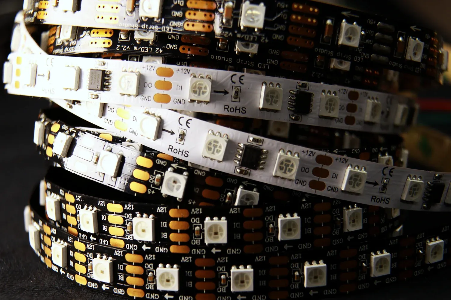
Wire with the power off, and connect data to the input end of the strip. The input end is marked DI or DIN, and the arrow on the strip points away from it. Data that goes into the output end does nothing.
- Unplug PSL2 from the mains before you touch the terminal.
- Connect GND to the strip’s ground and +POWER to its plus.
- Connect DATA to DI on the input end of the strip.
- Connect CLOCK only for four-wire strips such as APA102.
- Connect the backup line (BI), if the strip has one, to ground.
- Tighten the screws and pull each wire gently to check it holds.
How Do You Set the IC Type and Colour Order?
Set the IC type first, then the colour order, on the display or in the web interface. The default IC type covers the most common chips; the table above shows which others need their own setting.
Why Does Red Show Up as Green?
Red showing as green is a colour order problem, not a wiring fault. Many strips expect GRB instead of the default RGB. Change the colour order, run the colour test and check that red is red. For RGBW strips the list expands to 24 variants that include the white channel.
How Do You Test the Strip After Wiring?
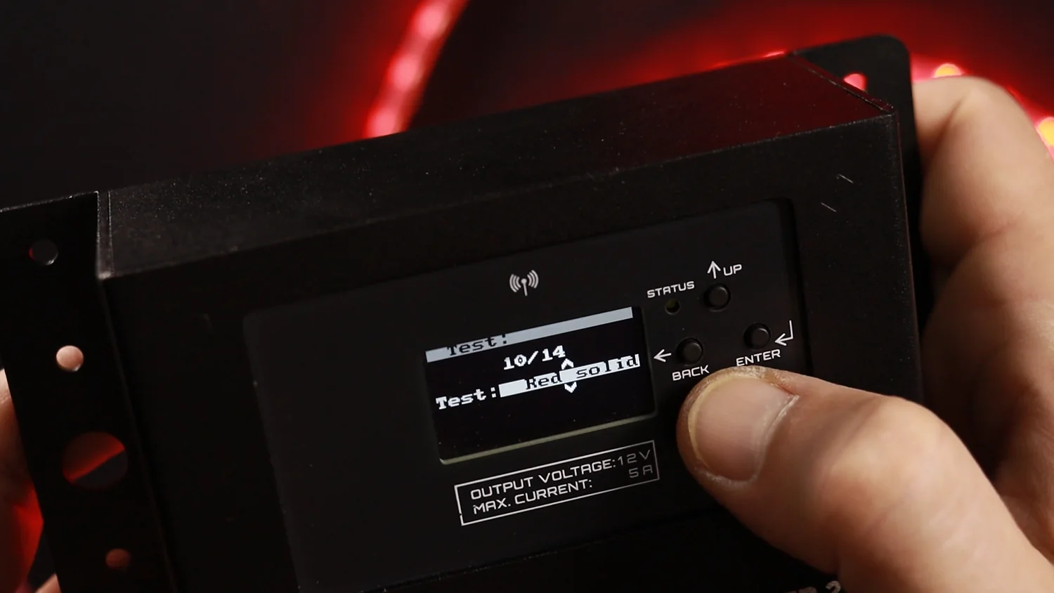
Use the colour test. It sends solid red, green, blue and white, dimming patterns and a snake to the whole output. The test always uses the maximum pixel count for the selected IC type, so every pixel should light up. If the strip lights only part way, check the data connection and the IC type.
How Much Strip Can One PSL2 Output Power?
One output controls about 17 m but powers only about 6.9 m. The signal and the power have separate limits, and on a typical strip the power runs out first.
| Limit | Calculation | Result on a 60 px/m, 8.64 W/m strip |
|---|---|---|
| Signal (RGB) | 1,024 px ÷ 60 px/m | about 17 m |
| Power, 12 V unit | 60 W ÷ 8.64 W/m | about 6.9 m |
| Power, 24 V unit | 60 W ÷ 8.64 W/m | about 6.9 m |
| Power, 5 V unit | 50 W ÷ strip W/m | depends on the 5 V strip |
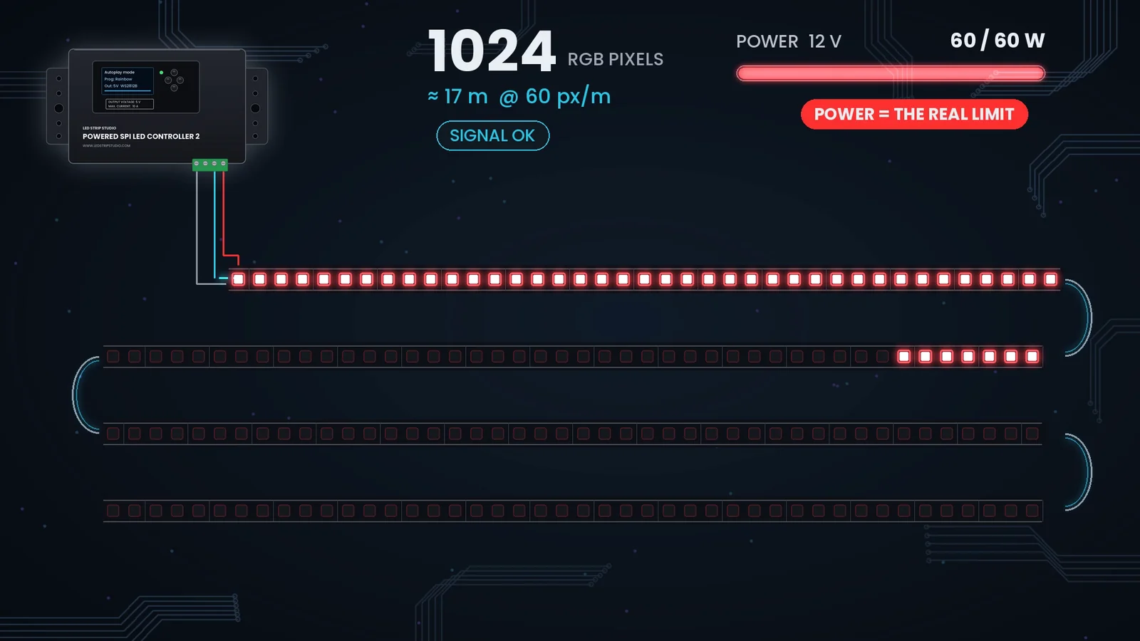
The 8.64 W/m figure is a typical 12 V WS2815 strip at full white. Your strip’s datasheet gives the exact number.
What Happens on a 10-Metre Strip?
Ten metres of the same strip draw 10 × 8.64 = 86.4 W at full white. That is 44 % over the 60 W of the 12 V unit. So for full white over 10 m you need an external supply. On a single output you can only run content at about 70 % of full white, for example by lowering the HW brightness in the device settings.
How Does Power Injection Fix Voltage Drop on PSL2?
Power injection feeds the strip at more than one point, so the far end gets the same voltage as the start. Voltage drop shows up as a yellow or dim end, and we saw it on just 10 metres of strip.
We tested it on two 5-metre reels in series, with the brightness turned down to stay within 60 W. Fed only from the start, the second reel was visibly dimmer. Then we switched PSL2 off, ran plus and ground from the same LED output to the middle and the far end, and switched it back on. Both reels were white end to end. With the middle feed removed, the second reel dimmed again.
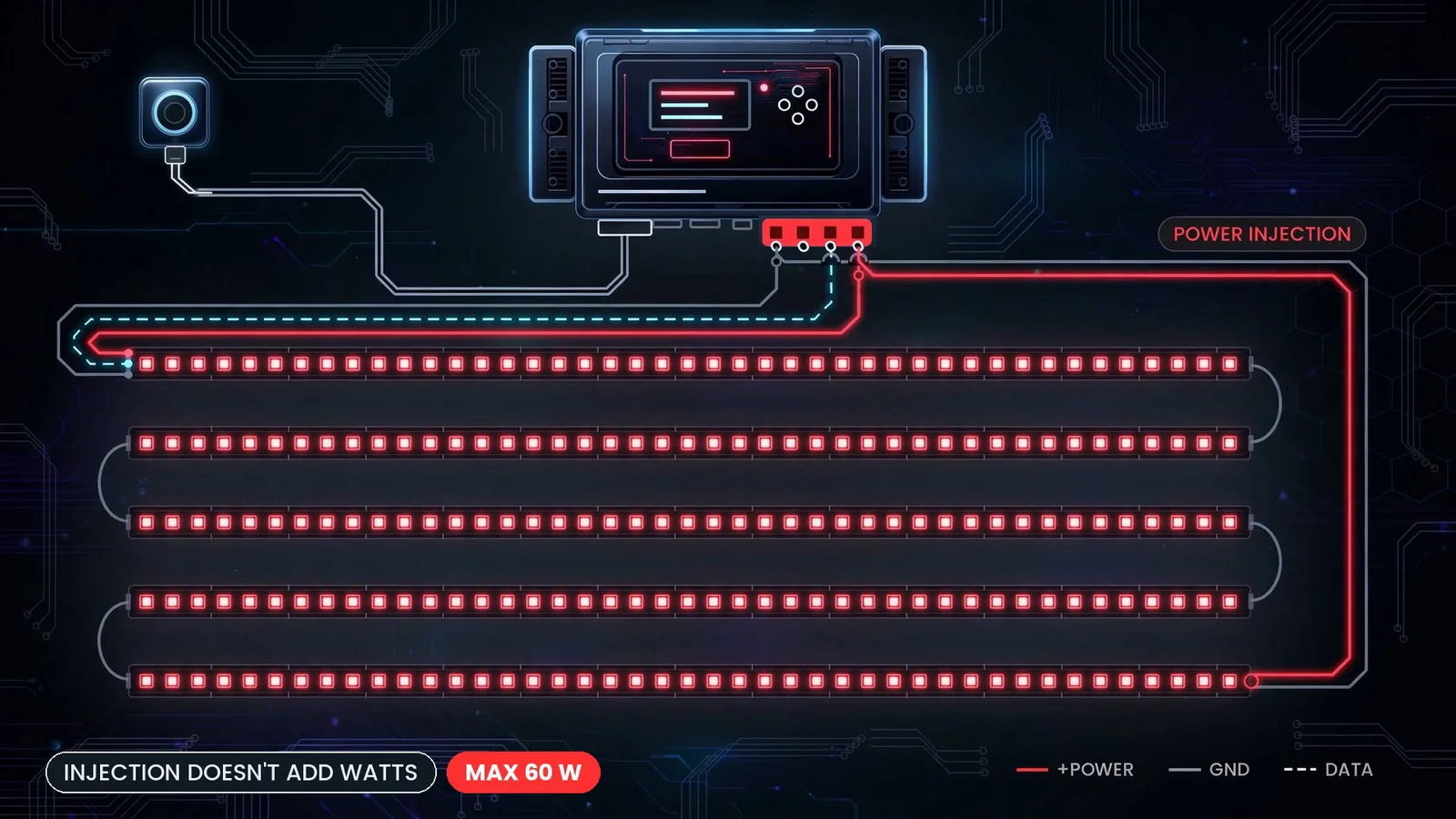
Remember the limit from the table. Injection does not add watts, so the whole strip still has to fit within 60 W.
When Do You Need an External Supply?
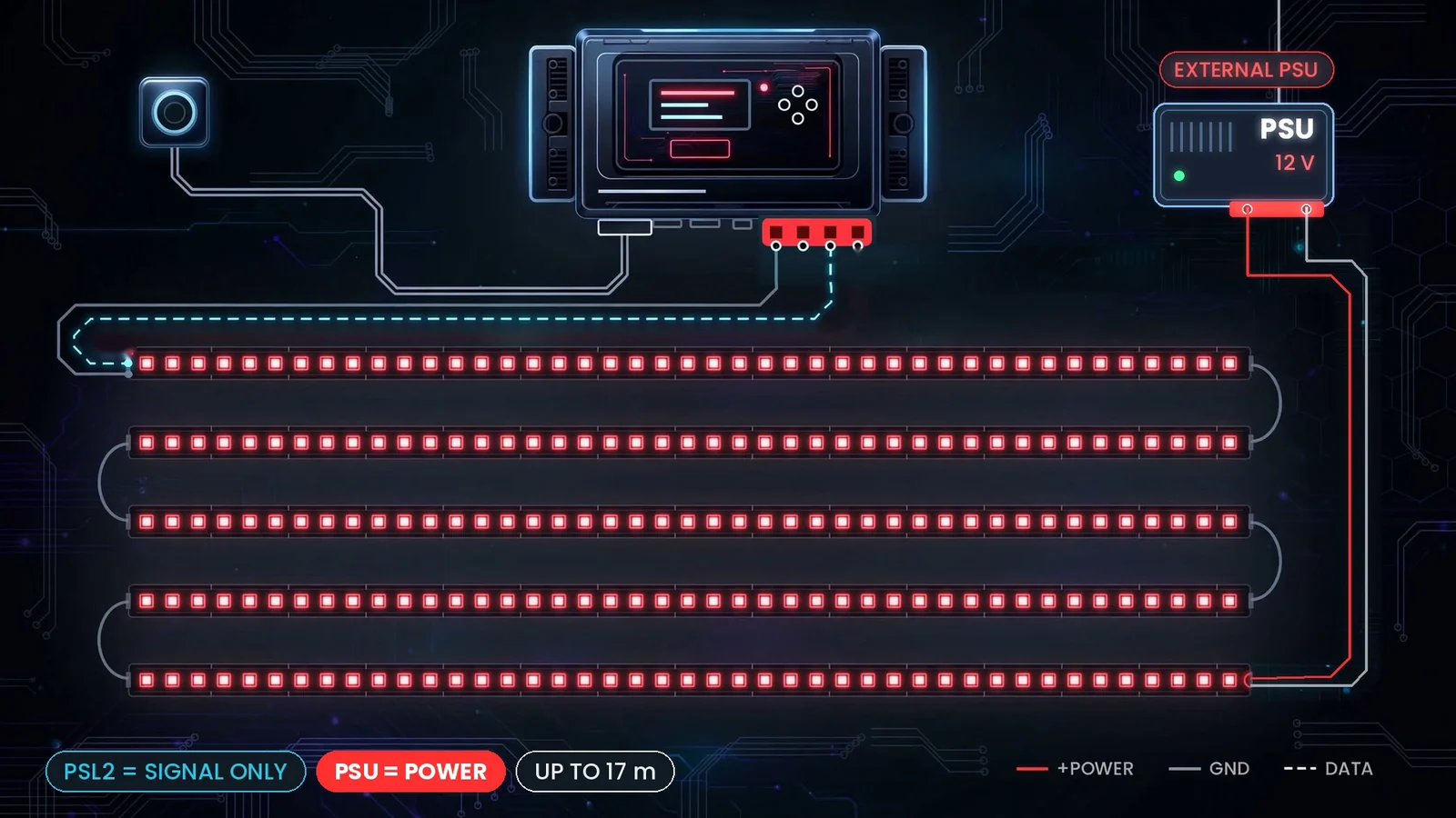
Add an external supply when the strip needs more than your variant delivers, like the 86.4 W of the 10-metre example. PSL2 then works only as a signal generator. It still controls the full 1,024 pixels, about 17 m at 60 px/m. The external supply powers the strip, and PSL2 keeps running from its own mains input.
Pick a supply with the same voltage as the strip. Its rating must be higher than the strip’s full-white load, so 10 m of 8.64 W/m strip needs a supply above 86.4 W.
How Do You Wire an External Supply to PSL2?
The manual shows one connection diagram for this setup. Power goes from the supply to the strip, and only the signal comes from PSL2.
- Switch everything off. Unplug PSL2 and the external supply.
- Connect +V of the supply to + on the strip.
- Connect −V of the supply to GND on the strip.
- Connect GND and DATA from the PSL2 LED output to GND and DIN on the strip. Four-wire strips also need CLOCK.
- Leave +POWER on PSL2 unconnected.
- Switch on the supply and PSL2, then run the colour test.
The GND wire from PSL2 must stay in place. The data signal needs a common ground with the strip, so the strip GND connects to both PSL2 and the supply.
The manual is strict on one point: never connect two different power sources to the power input and the LED output at once. In practice, the +V of the external supply never goes to +POWER on PSL2.
How Long Can the Signal Cable Be?
Keep the data cable between PSL2 and the strip as short as possible. Up to 1 m is ideal and up to 10 m can still work. For longer runs we strongly recommend a pair of The Symmetrizer units, which carry the signal over a twisted pair for 100 m and more. Our guide to long-distance SPI signal explains why.
Which PSL2 Wiring Mistakes Cost the Most Time?
Most first-day problems come from wiring and settings, not from the hardware. These are the ones we see most often:
- Wiring with the power on. Unplug PSL2 before every change, including when you add injection wires.
- Data on the wrong end. Data goes to DI. Follow the arrow on the strip.
- Wrong strip voltage. The strip voltage must match the label on PSL2.
- Blaming the wiring for wrong colours. Swapped red and green is the colour order.
- Expecting injection to add power. It only evens out the voltage. The 60 W limit stays.
- +POWER connected next to an external supply. With an external supply, PSL2 sends only GND and DATA.
- A long bare data cable. Over 10 m, use The Symmetrizer.
Next, we connect PSL2 to Wi-Fi and control it from a phone. Planning a bigger installation and not sure about the power? Book a free consultation and we will help you size it.
Powered SPI LED Controller 2
Pixel LED controller with a built-in power supply, up to 1,024 RGB pixels.
Summary
PSL2 wiring takes four wires: GND, CLOCK, DATA and +POWER, connected with the unit switched off. Three-wire strips such as WS2812B use data only, four-wire strips such as APA102 also use clock, and data always goes to the DATA IN end of the strip. The default IC type covers WS2811, WS2812B and SK6812; wrong colours are fixed with the colour order. One output controls 1,024 RGB pixels, about 17 m at 60 px/m, but the 12 V unit powers only 60 W, about 6.9 m of an 8.64 W/m strip. Power injection fixes voltage drop but adds no watts. Beyond 60 W, add an external supply for the strip and connect only GND and DATA from PSL2.