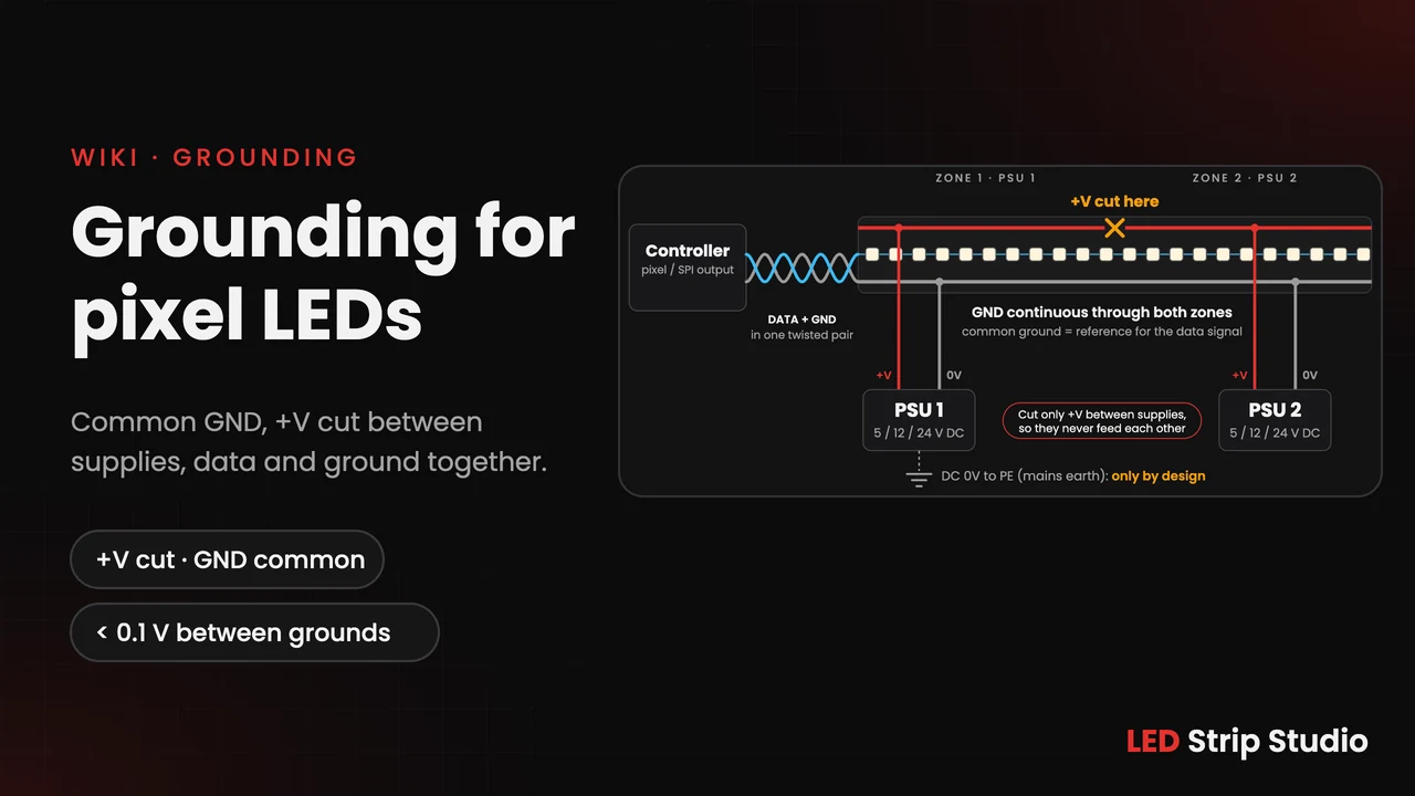
Grounding is one of the most important parts of a pixel LED installation. It is also something that is often overlooked.
Many common problems, such as flickering, wrong colors or pixels that stop responding, can be caused by poor grounding. A missing or loose ground connection can affect the whole system.
Let’s look at how grounding works and how to avoid common problems.
What Wires Do I Need for a Pixel LED Strip?
Some pixel LED strips have four connections, while others use only three. The labels may vary depending on the manufacturer, so always check the datasheet.
- +V (VCC): Positive power supply, usually 5V or 12V.
- GND (0V): Ground or negative power connection. It also provides the reference for the data signal.
- DATA (DIN): Carries the color information to the LEDs.
- CLOCK (CKI): Used on some LED strips, such as APA102 and SK9822. It controls the timing of the data signal.
There are a few important things to remember when connecting everything:
- Always connect ground together with data when using standard single-ended data transmission. The data signal needs a ground reference to work correctly. Without it, the LEDs may receive incorrect data.
- Never disconnect ground between power zones without providing an alternative signal reference. You can disconnect the positive (+V) wire between two power supplies, but the ground connection must remain for standard single-ended data signals. Isolated or differential interfaces may use a different wiring arrangement.
- Do not automatically connect DC ground to mains earth (PE). Whether they should be connected depends on the power supply design and the requirements of the installation. Any connection must follow the manufacturer’s documentation and applicable safety regulations. Never disconnect protective earth from the metal chassis of Class I equipment.
Why Does My Pixel LED Strip Flicker?
In many cases, poor grounding can be the reason.
Pixel LEDs read the data signal by comparing its voltage with their local ground. If the ground voltage is unstable or different in different parts of the installation, the LEDs may read the data incorrectly.
Common problems and their causes:
| What You See | Possible Cause |
|---|---|
| Random flickering | The controller and LED strip do not share a good ground connection, or the data signal is affected by electrical noise. |
| Colors change along the strip | Voltage drop or different ground potentials between power supplies. |
| Pixels freeze or turn off | Missing ground reference, disconnected ground or insufficient power. |
| Slow flickering, stripes or humming | Electrical noise, improper grounding or ground loops. |
| LEDs or chips fail too early | Voltage spikes or incorrect power supply conditions. |
5 Simple Rules to Avoid Grounding Problems
1. Connect All Grounds Together
For standard single-ended data transmission, connect the 0V outputs of the power supplies and controller to a common ground network.
Even if your power supplies are several meters apart, their ground connections should be properly referenced.
Also, always run a separate ground wire alongside the data cable from the controller to the first pixel.
For isolated or differential interfaces, follow the manufacturer’s wiring instructions.
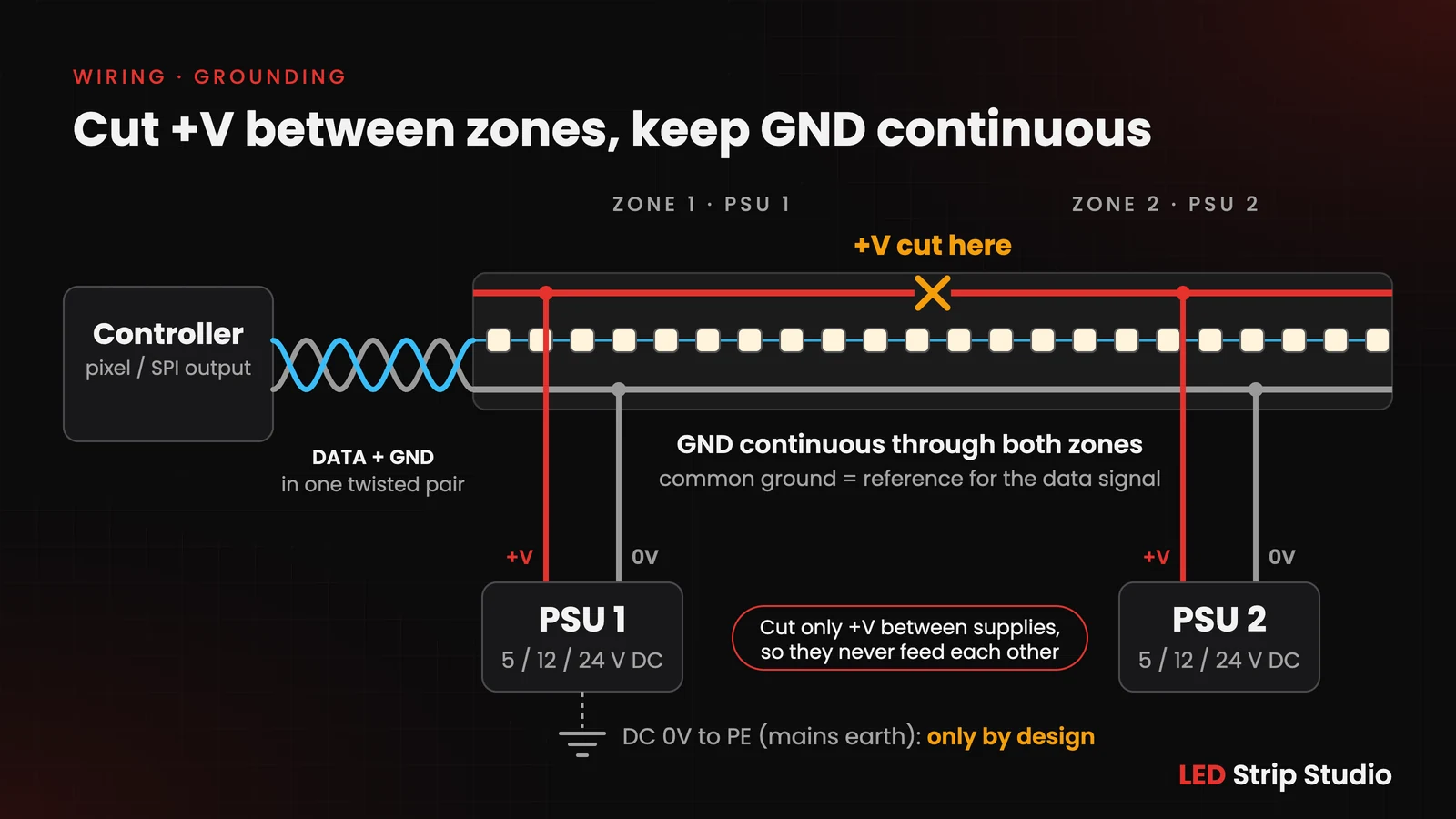
2. Never Disconnect Ground Between Power Zones
When using multiple power supplies, disconnect the +V wire between them to prevent one power supply from feeding power into another.
However, keep the ground wire connected between all zones when using standard single-ended data transmission.
3. Keep DC Ground and Mains Earth Properly Connected
Do not automatically connect DC ground to mains earth (PE). Whether they should be connected depends on the power supply design and the requirements of the installation.
Avoid connecting DC ground to PE at multiple points without a proper system design, as this can create ground loops and cause unwanted electrical noise.
Protective earth must remain properly connected to the metal chassis of equipment that requires it.
4. Always Run Data and Ground Together
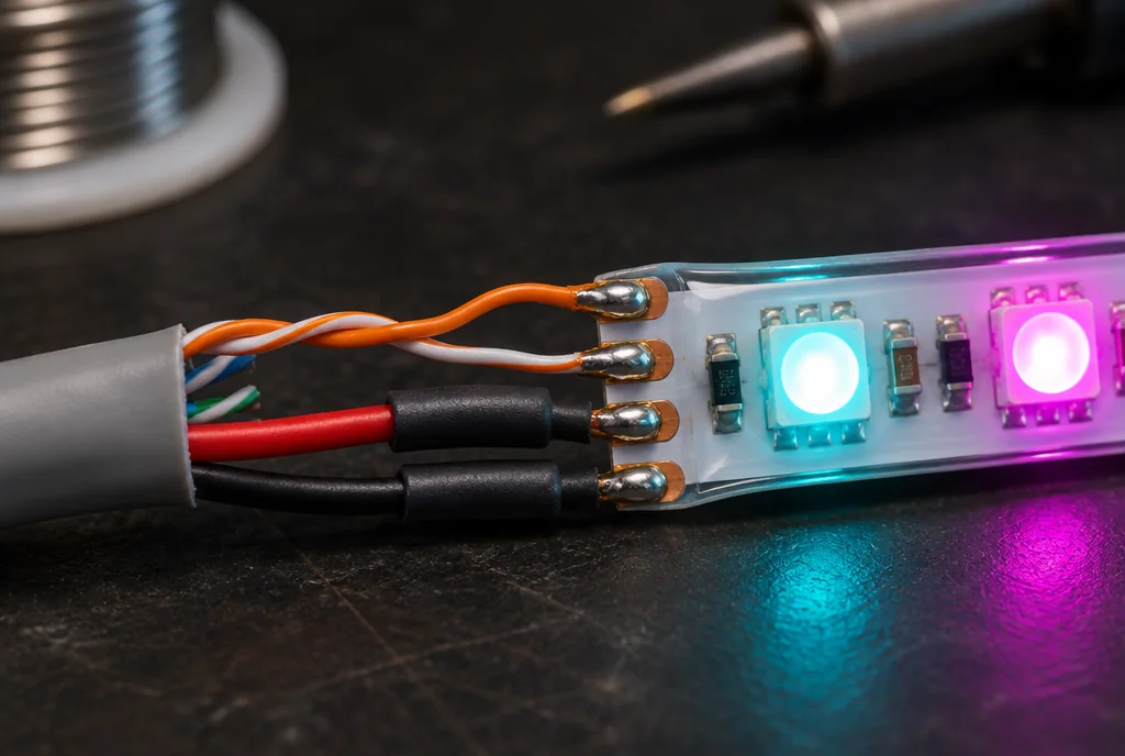
Use twisted-pair cables such as Cat5e or Cat6, or shielded 24 AWG twisted-pair cable.
Run the data signal in one twisted pair together with a ground wire.
For LED strips that use both data and clock signals, use a second twisted pair for the clock, with an appropriate ground reference according to the interface requirements.
5. Connect Cable Shielding Correctly
If you use shielded cables, connect the shield according to the system design and manufacturer’s recommendations.
In many installations, the shield is connected to the controller chassis or mains earth at one end only, usually at the controller. Other installations may require a different arrangement.
Do not connect the cable shield directly to the data ground.
How to Check Grounding with a Multimeter
A multimeter can help you find grounding problems before they cause issues.
Here are four simple tests.
1. Check Ground Continuity (POWER OFF)
Measure the resistance between the controller’s 0V terminal and the 0V connection at the far end of each LED strip.
The reading should be as low as possible. Below 1 ohm can be a useful target for short, properly sized cables.
The actual reading depends on cable length, wire size, connection quality and the resistance of the multimeter leads.
2. Check the Connection to Mains Earth (POWER OFF)
Measure the resistance between DC 0V and the mains earth connection.
If the system has an isolated DC output, you may normally see an open circuit or very high resistance.
However, internal power supply components can affect the reading. A resistance measurement alone does not reliably confirm galvanic isolation, so always check the manufacturer’s documentation.
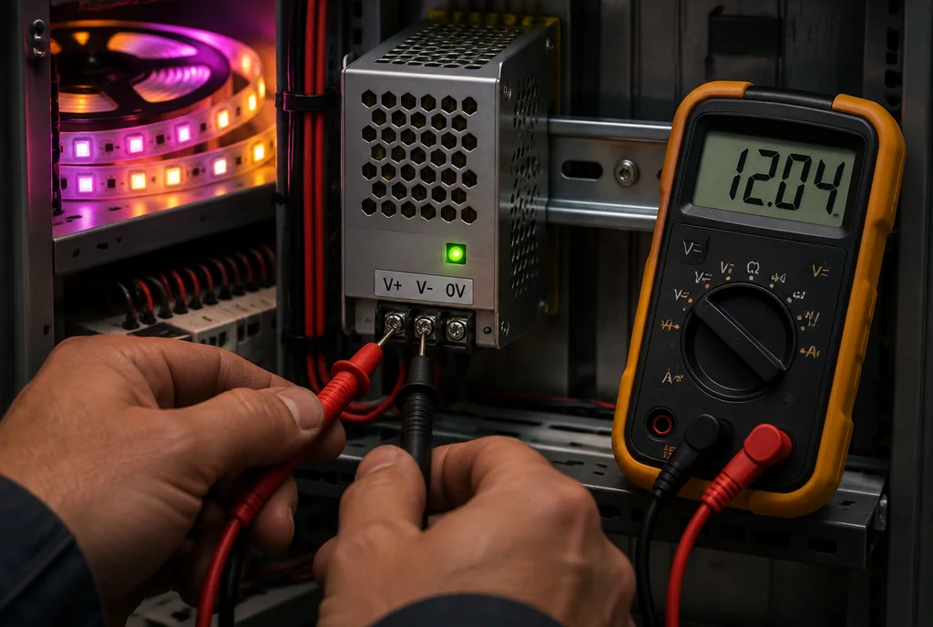
3. Check Ground Voltage Differences (POWER ON, LEDs OFF)
Measure the DC voltage between the controller’s 0V and the 0V terminal of each power supply.
- Below 0.1V: Good.
- Above 0.3V: Check the ground cables and connections.
A large difference usually means that the ground cable is too thin, too long or not properly connected.
These values are general guidelines, not universal limits for every installation.
4. Check Grounding Under Full Load (POWER ON, ALL LEDs FULL WHITE)
Measure the voltage between the controller’s 0V and the 0V connection at the beginning of each LED strip.
As a general guideline, try to keep it below 0.5V.
If it is above 0.8V, check the ground cable size, cable length, connections and power distribution.
A large voltage difference can cause problems with the data signal’s ground reference, but it does not automatically mean that too much current is flowing through the signal ground.
These values are guidelines and may vary depending on the installation.
Important: Only perform electrical measurements if you know how to use a multimeter safely. Never measure resistance on a powered circuit.
How to Fix CRC Errors on SPI with Long Cables?
CRC errors mean that the data received by the LED controller or decoder is not the same as the data that was sent.
With long SPI cables, this is often caused by electrical noise, poor grounding or a signal that is too weak for the cable length.
Here are five things you can do:
Step 1: Use Shielded Twisted-Pair Cables
Shielded cables help protect the data signal from electrical noise coming from nearby power cables, dimmers and other equipment.
Step 2: Connect the Shield Correctly
Connect the cable shield according to the system design. In many cases, it is connected to the controller chassis or mains earth at the controller end only.
Do not connect the shield directly to the data ground.
Step 3: Use a Line Driver for Longer Cables
Standard single-ended SPI signals are not designed for long cable distances. As a general rule, keep these connections to around 3 meters or less, depending on the cable, transmission speed and electrical environment.
For longer distances, use a differential signal converter such as The Symmetrizer.
Differential transmission can support much longer cable runs, potentially up to around 500 meters with suitable equipment and cabling.
This is not a native feature of the SPI protocol. The signals are transmitted over a differential interface and converted back to SPI at the receiving end.
The actual distance depends on the converter, cable type, transmission speed and electromagnetic environment. Always check the manufacturer’s technical documentation for supported distances and operating conditions.
Step 4: Run a Ground Reference Alongside the Differential Signal
Even when using differential signals, some systems require a ground reference between the transmitter and receiver.
Run a ground wire alongside the A/B (or +/-) signal pair when required by the manufacturer’s wiring instructions. This helps keep the equipment within its allowed voltage range.
Step 5: Check the Ground Connections First
Before replacing controllers, cables or other hardware, check the grounding.
Use the multimeter tests described above. You may find that fixing a loose or missing ground connection is enough to solve the CRC errors.
Final Thoughts
Grounding can be one of the most frustrating parts of a pixel LED installation. It can cause all kinds of problems, from random flickering to data errors and pixels that stop working.
The good news is that most of these problems can be avoided with proper wiring.
Keep the ground reference correct, run ground alongside data, use suitable cables and check your connections before switching the system on.
A little extra attention to grounding at the beginning can save you a lot of troubleshooting later.
Frequently Asked Questions
Can I disconnect GND between two power supplies in a pixel LED installation?
Not with standard single-ended data. Cut only the +V wire between the supplies so they never feed each other, and keep GND connected, because the data signal needs that shared reference.
Should the 0V of my LED power supplies be connected to protective earth (PE)?
Not automatically. It depends on the power supply design and the installation's requirements, so follow the manufacturer's documentation and the safety regulations. Connecting DC ground to PE at several points without a proper design can create ground loops.
What voltage between grounds is acceptable?
As a guideline, below 0.1 V between the controller's 0V and each power supply's 0V with the LEDs off, and below 0.5 V at the start of each strip at full white. Above 0.3 V or 0.8 V respectively, check the ground cables and connections.
Which cable should I use for the data line?
Twisted pair, such as Cat5e or Cat6, or shielded 24 AWG twisted-pair cable. Put the data signal and a ground wire in one pair; clocked strips like APA102 use a second pair for the clock.
Do differential signals still need a ground reference?
Some systems do. Run a ground wire alongside the A/B pair whenever the manufacturer's wiring instructions ask for it, so the equipment stays within its allowed voltage range.
Summary
Pixel LEDs read the data signal against their local ground, so with standard single-ended data the controller and every power supply need a common ground, and a ground wire must run alongside the data. With standard single-ended data transmission, keep GND connected between power zones and isolate only the +V connections. Connect DC ground to mains earth (PE) only where the supply design and safety regulations call for it. As a guideline, aim for under 1 Ω of ground resistance, under 0.1 V between grounds with the LEDs off and under 0.5 V at full white. For longer SPI runs, consider using a suitable differential converter such as The Symmetrizer.