


Description
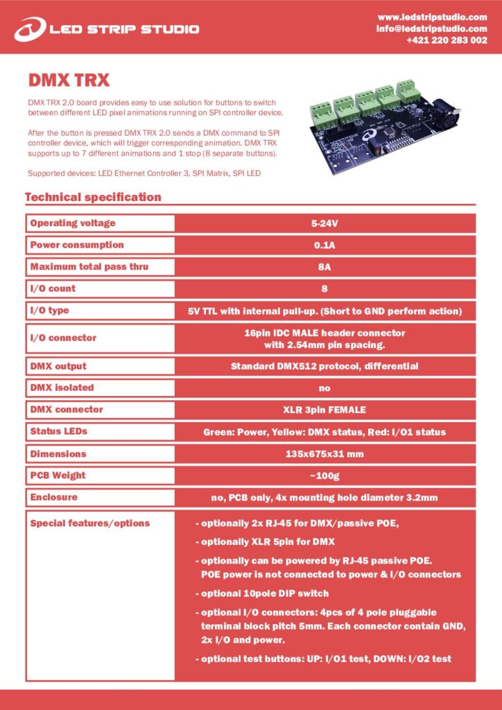
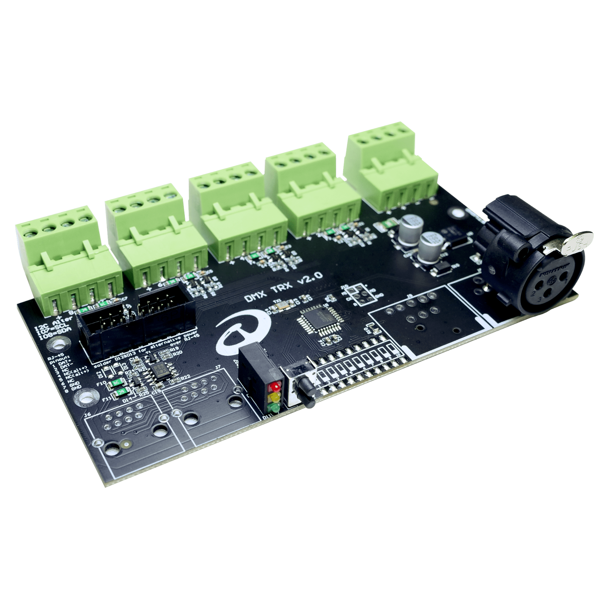
Sometimes the whole brief is a button on the wall next to the light switch. No console, no laptop in a cupboard. Nobody needs training to change the scene. That is the job DMX TRX 2.0 does. It is a DMX trigger board with eight buttons, eight commands, and animations already waiting on the controller’s SD card.
How does the DMX trigger board work?
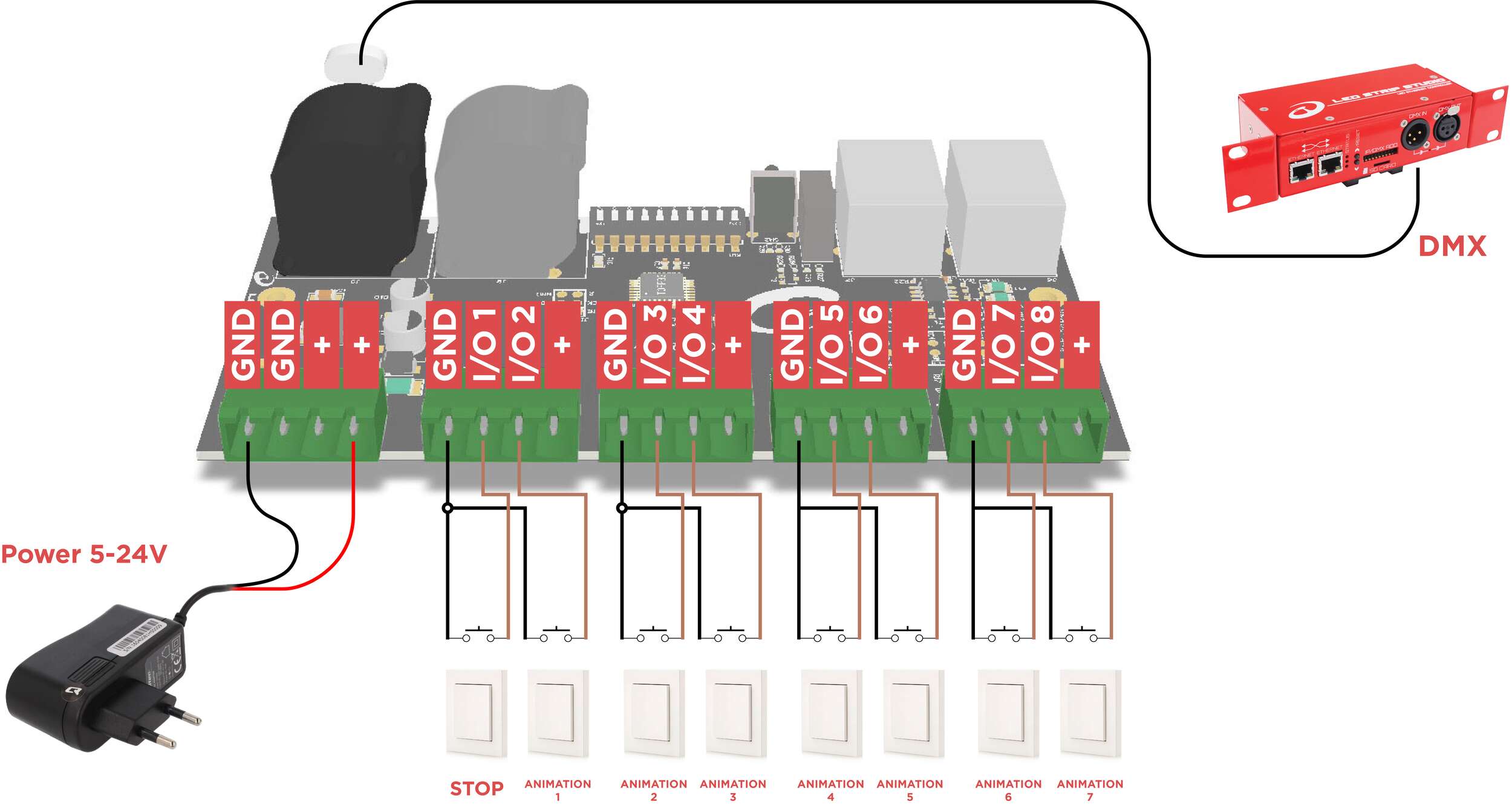
First, wire up to eight buttons. Then connect the board’s DMX output to an LED Ethernet Controller 3, SPI Matrix or SPI LED Controller. From there it is simple. Each press sends a DMX command that calls up an animation already stored on the controller’s SD card. Seven buttons play seven animations, and the eighth stops playback. For more detail, see our wiki on how SD-card mode triggers animations over DMX.
Wiring buttons to the 5 V TTL inputs
The inputs are 5 V TTL with internal pull-up. So triggering just means shorting a pin to ground. In practice, almost anything that closes a contact will work: push buttons, illuminated wall switches, key switches, even a relay output from a building system. All eight channels leave on one 16-pin IDC ribbon header. For flying leads, optional 4-pole terminal blocks are also available.
Which controllers does the DMX TRX work with?
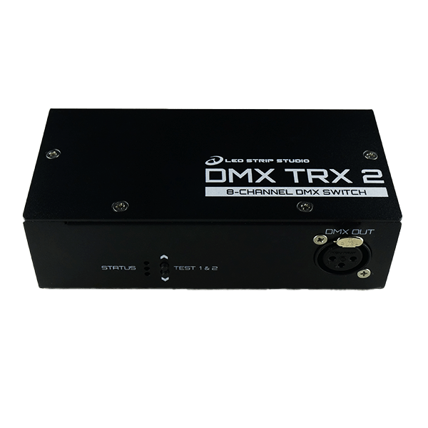
Three controllers are supported: LED Ethernet Controller 3, SPI Matrix and SPI LED Controller. The DMX trigger board is a standard DMX512 source. It sits on a 3-pin female XLR, with RJ-45 and 5-pin XLR as options. An optional 10-pole DIP switch sets the DMX address.
Power, mounting and status LEDs
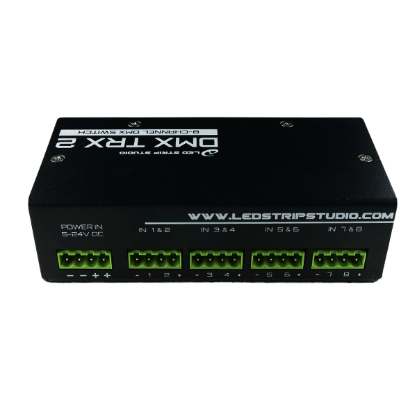
Power is undemanding: 5 to 24 V, and only 0.1 A for the board itself. As a result, it usually shares the supply the installation already has. When a second cable is awkward, the optional RJ-45 version is the answer. It accepts passive PoE, kept isolated from the I/O circuits. For commissioning, three status LEDs keep things simple: green for power, yellow for DMX activity, red for the first input.
DMX TRX 2.0 specifications at a glance
- 8 inputs — 7 animations plus 1 stop
- DMX512 output on 3-pin female XLR, optional RJ-45 or 5-pin XLR
- 5 V TTL inputs with internal pull-up, triggered by shorting to GND
- 5–24 V working voltage, 0.1 A own consumption
- Optional 10-pole DIP switch for setting the DMX address
- Open PCB, 135 x 67.5 x 31 mm, four 3.2 mm mounting holes
In short, the DMX trigger board ships as a bare PCB, ready to build into your own panel.