


Description
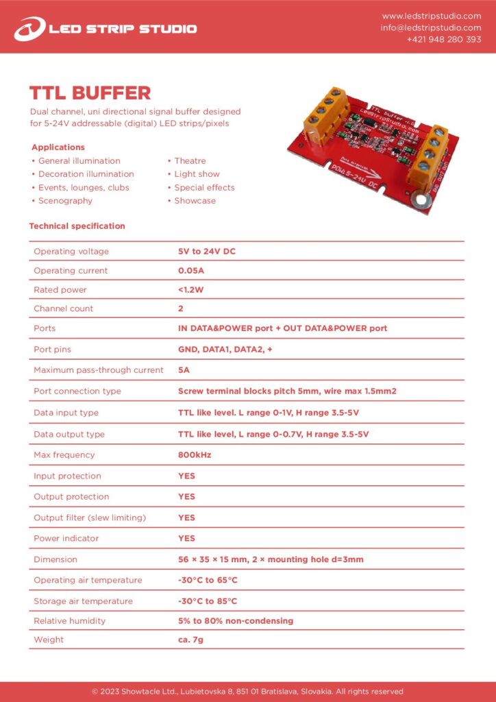
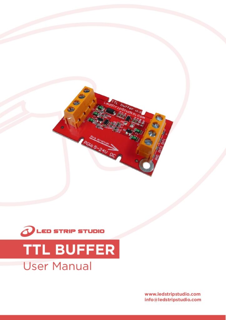
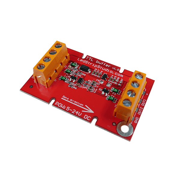
The TTL Signal Buffer regenerates the data signal on its way to your digital addressable LED strips, so the cable between the controller and the first pixel can be longer. Two uni-directional channels, an operating range of 5 to 24 V DC, and protection on both the input and the output side. Price is per pack of 10 units.
What does a TTL signal buffer do?
A TTL data line does not travel well. Every extra metre of cable adds capacitance, the pulse edges grow slower and rounder, and at some point the first pixel reads noise instead of a frame. Flickering, colour errors and a strip that only works when you touch the cable all start here.
The buffer takes that tired signal in and sends a clean, full-level copy out. Put one at the far end of a long run, or chain several along a very long one, and the pixels see the same crisp signal the controller sent.
Two independent channels in one module
Each port carries two data lines, DATA1 and DATA2. One module therefore handles two separate strip runs that leave the same point, instead of asking you to buy and mount two devices.
One direction only
Data enters on the IN port and leaves on the OUT port, so wire it that way round. The module is a repeater sitting in the line between controller and pixels — it does not split a signal, and it does not convert between protocols.
Which voltage does the TTL signal buffer run on?
Anything from 5 to 24 V DC, which covers 5 V, 12 V and 24 V pixel systems on the same part number. The module itself draws 0.05 A and under 1.2 W, so it adds nothing meaningful to your power budget.
Power travels with the data
Both ports carry GND, DATA1, DATA2 and the supply rail together, so a single four-wire cable feeds the next section of the installation. The board passes up to 5 A through, and that figure is your limit — for anything heavier, inject power locally at the strip and use the buffer for the data.
How do you wire the TTL signal buffer?
Both ports are screw terminal blocks with 5 mm pitch, taking wire up to 1.5 mm². Nothing to crimp, no proprietary plug, and a connection you can undo with a screwdriver when the layout changes on site.
Small enough to hide in an electrical box
The board measures 56 × 35 × 15 mm and weighs about 7 grams. It fits a standard electrical box, which is how you get a weather-proof joint outdoors or in a damp space — the box does the sealing, the buffer does the signal.
What keeps the signal clean?
Input protection and output protection are both fitted, so a wiring mistake or a surge on a long line meets the buffer first rather than your controller or your pixels. The module accepts TTL-like levels with a low range of 0 to 1 V and a high range of 3.5 to 5 V, and drives a tighter 0 to 0.7 V low with the same 3.5 to 5 V high.
An output filter that limits the slew rate
The output stage deliberately softens its edges instead of switching as hard as it can. Gentler edges mean less ringing and less radiated noise on a long cable — useful in racks and trusses where data and power run side by side. Maximum frequency is 800 kHz, which covers the usual 800 kHz addressable protocols.
Where does the TTL signal buffer belong?
Anywhere the distance beats the signal: architectural runs along a facade, stage and club installations, LED screens built from many segments, and any layout where the controller has to live in a rack far from the pixels. It pairs with LEC 3, SPI LED Controller and REACTIVO 2, and complements THE SYMMETRIZER, which converts to a differential pair for the really long hauls. Ten units per pack means one for every problem spot in the job, with a couple left in the spares box. Ask our support team if you are not sure how many your run needs.