


Description
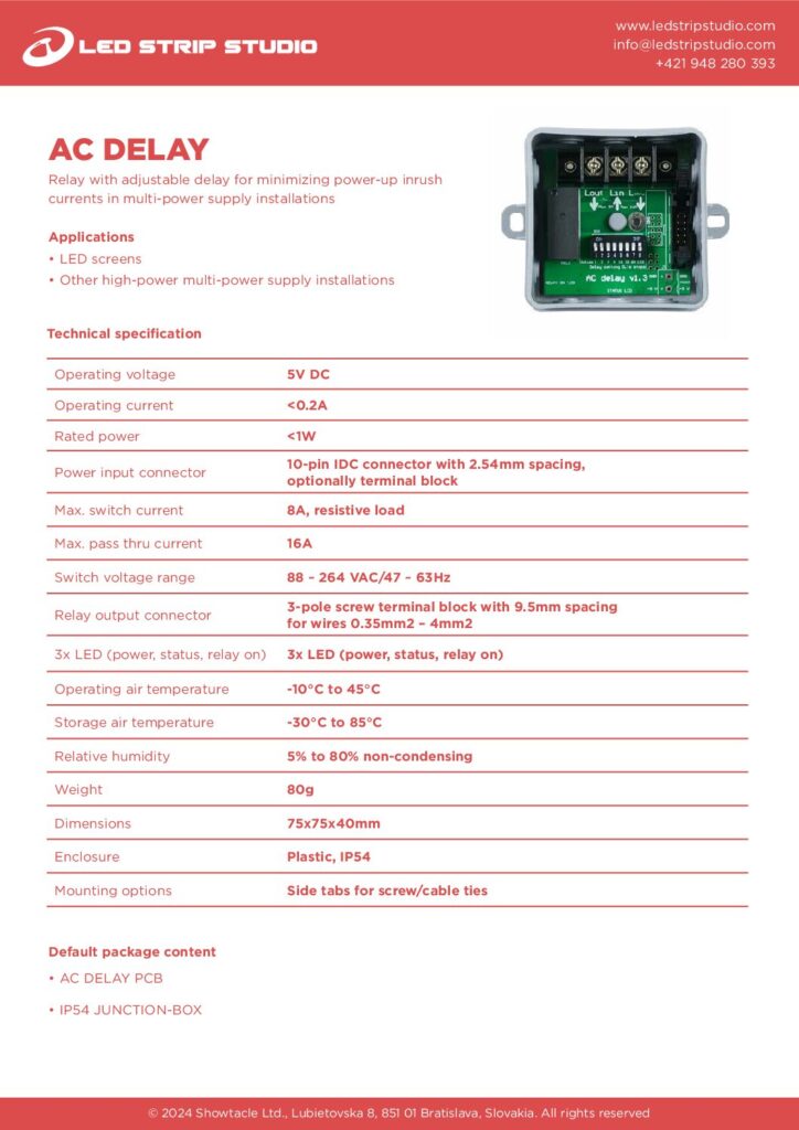
The AC Delay postpones the power-up of a power source, so several supplies never start in the same instant. A relay switches mains up to 230 V AC and the terminal block passes up to 16 A. Above all, it keeps a large LED screen from tripping its own breaker at switch-on.
What problem does the AC Delay solve?
Every switch-mode power supply draws a short current peak when it starts. One unit is harmless. Twenty units behind one breaker are not, because the peaks add up. The breaker reads that sum as a fault and cuts the whole installation.
Inrush current on large LED screens
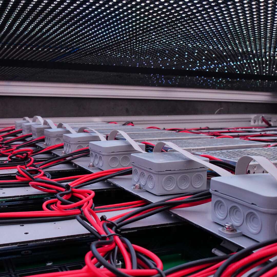
An LED screen is built from many panels, and each panel group has its own power supply. Give every group an AC Delay with a different delay value. The peaks then arrive one after another, and the breaker stays on.
It separates the peaks, it does not limit them
The module is a timed relay, not a soft starter. Each supply still draws its own peak at its own moment. The AC Delay only makes sure those moments do not coincide, because coincidence is what the breaker reacts to.
How do you set the delay time?
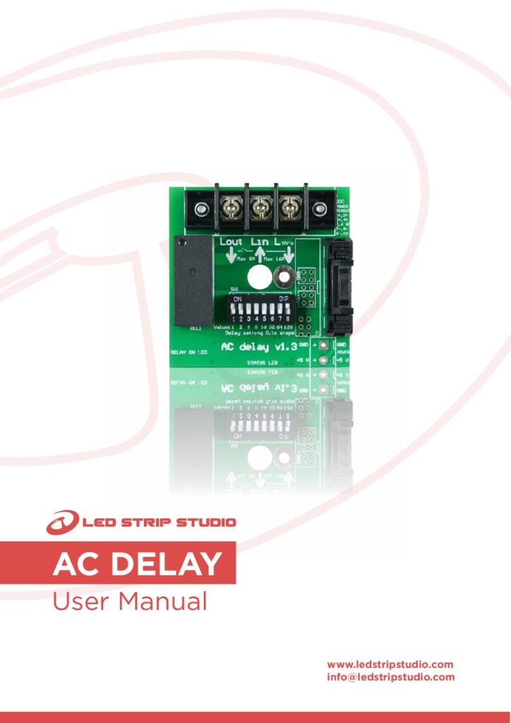
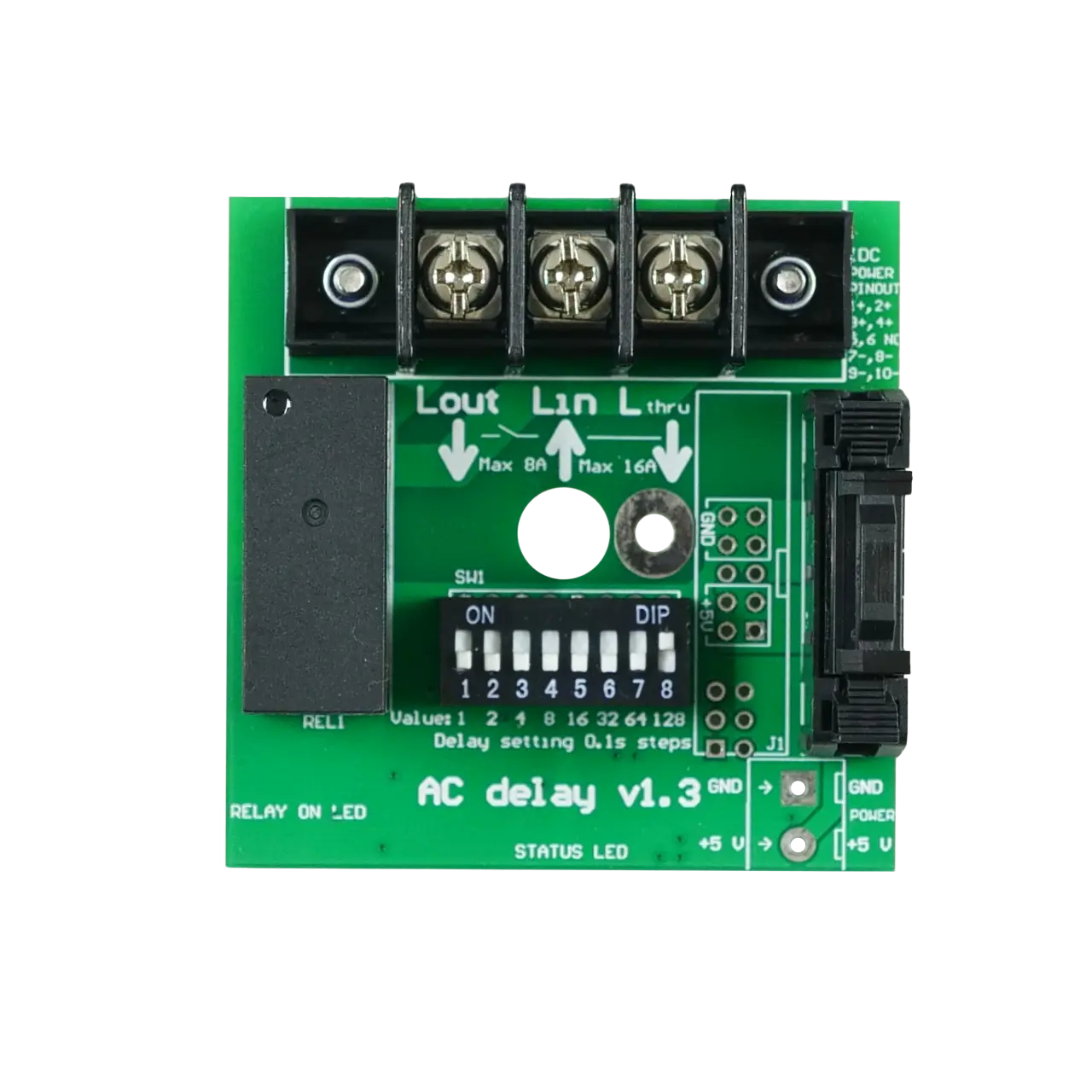
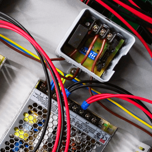
An 8-bit DIP switch on the board sets the delay. You set it once, and the module keeps the value — no display, no menu and no configuration software. Stagger the values across the rack and the supplies start in sequence.
Three LEDs show what the module is doing
The board carries three indicators: power, status and relay on. You therefore see at a glance whether the module has its 5 V, whether it is still counting, and whether the relay has already closed.
How is the AC Delay wired into a rack?
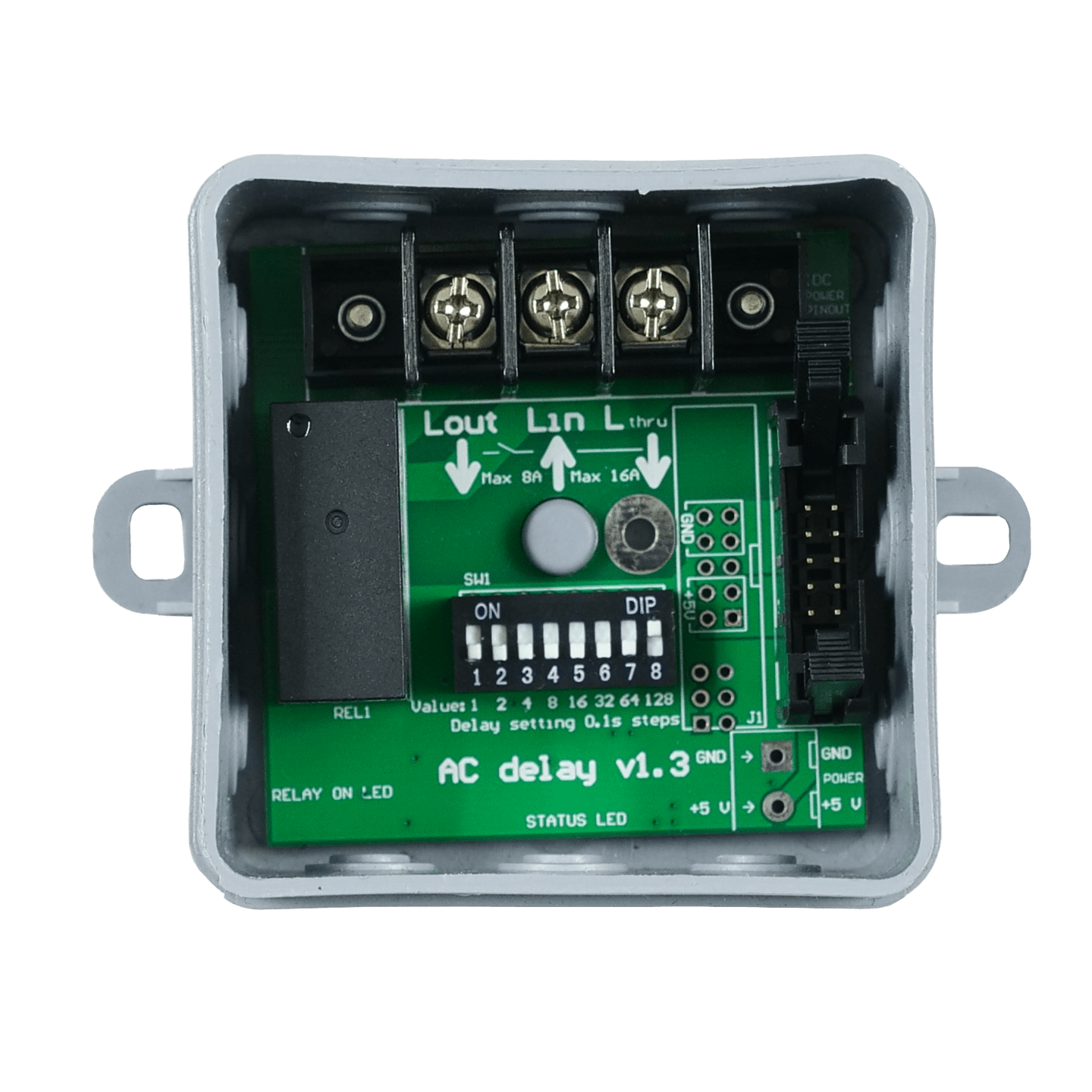
Mains goes to a 3-pole screw terminal with 9.5 mm pitch, which takes wires from 0.35 mm² to 4 mm². The relay switches up to 8 A of resistive load, while the terminal block passes up to 16 A in total. Size your load against the 8 A switching limit, not against the pass-through figure.
Two ways to power the trigger side
The module itself runs on 5 V DC and draws about 0.5 W. Feed it through the 2-pole screw terminal with 5 mm pitch, for wires under 1.5 mm². Or use the latched 10-pin IDC header, which suits a ribbon cable feeding several modules from one 5 V source.
AC Delay specifications at a glance
- Relay output, up to 230 V AC and 8 A of resistive switching
- 16 A maximum total pass-through current
- Mains on a 3-pole screw terminal, 9.5 mm pitch, wires 0.35–4 mm²
- 5 V DC supply, typically 0.5 W
- Trigger power on a 2-pole screw terminal or a latched 10-pin IDC header
- Delay on an 8-bit DIP switch, with three indicator LEDs
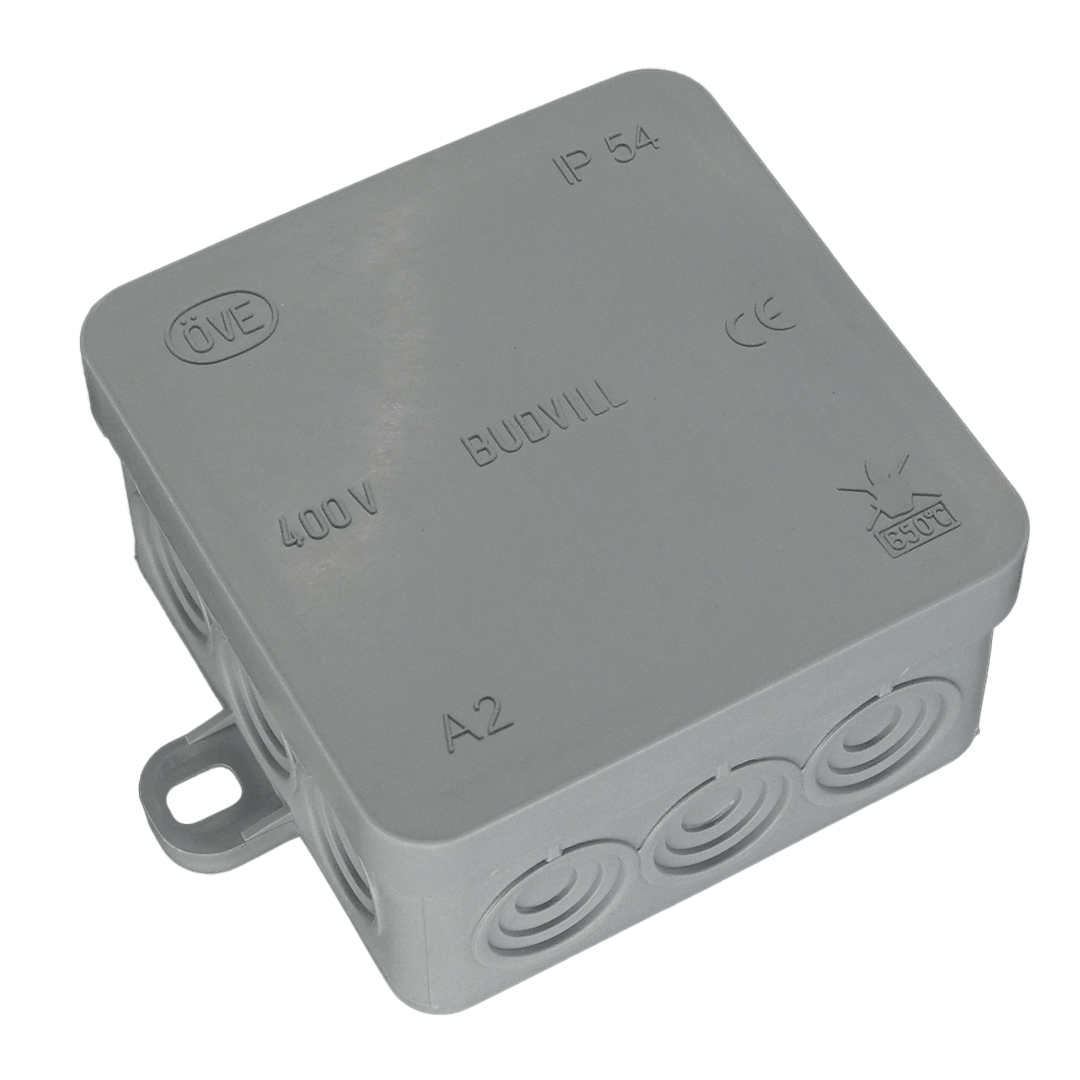
- Plastic box, 60 × 60 × 30 mm, 35 g
Where does the AC Delay belong?
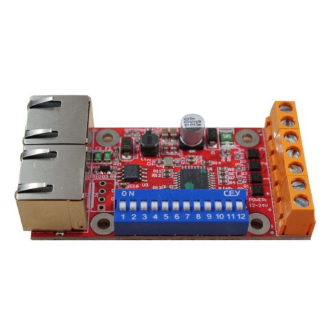
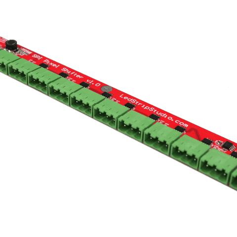
LED screens lead the list, because a screen multiplies one small peak by the number of panels. Touring racks and fixed installations gain the same benefit wherever many supplies share one circuit. Take the 5 V trigger from the rail already in the rack, next to a LEC 3 or a SPI LED Controller running LED Strip Studio software. Ask our support team if you are unsure how many supplies one circuit can take.